SLYA076 july 2023 TMAG5273
2.3.3 Implementation Option 2: Floating Magnet with Array of Latches or Switches
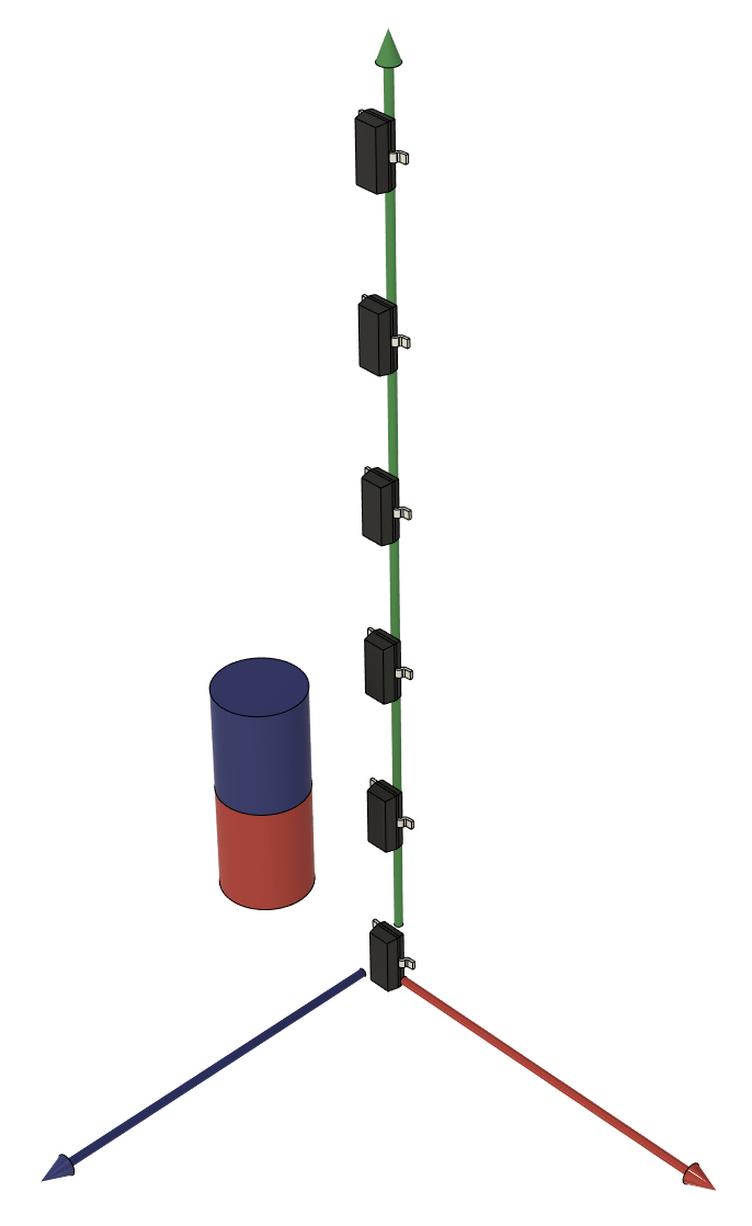
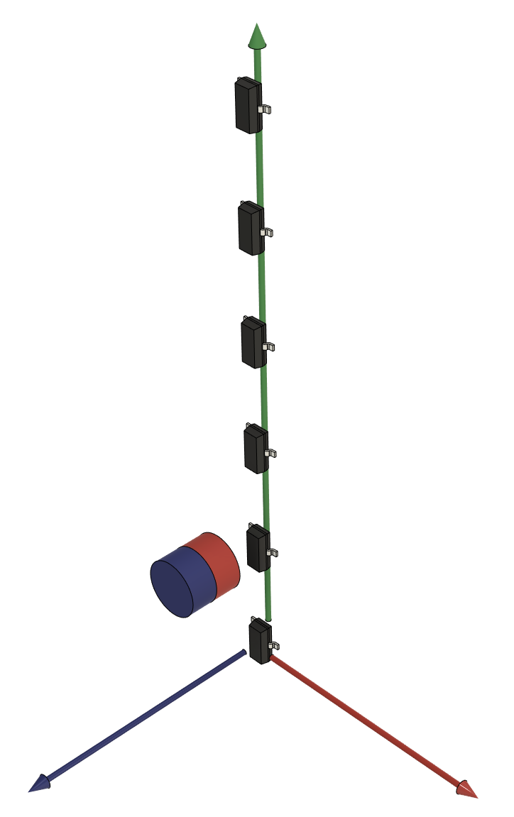
An array of sensors can be used to detect specific liquid positions as a magnet passes each sensor. Hall-effect latches can be used with a sideways magnet as shown in Figure 2-6 if it is desired for the sensors to stay active when the liquid is above that sensor. It can be useful to know the liquid level region when the magnet is between the sensors without needing to keep track of the most recently detected level.
Hall-effect switches can be used with a magnet facing the sensors as shown in Figure 2-7. This is useful if the system only needs to know when the liquid has reached a specific level and doesn't need to know the liquid level region when the magnet is between sensors.
Either setup needs a sensor for each liquid level position to detect, and thus a PCB running the length of the detection region. However, this design can allow for a smaller magnet than the vertically floating magnet setup.
 Figure 2-6 Hall Latch Array
 Figure 2-7 Hall Switch Array