SLYA076 july 2023 TMAG5273
3 Functional Demo Design
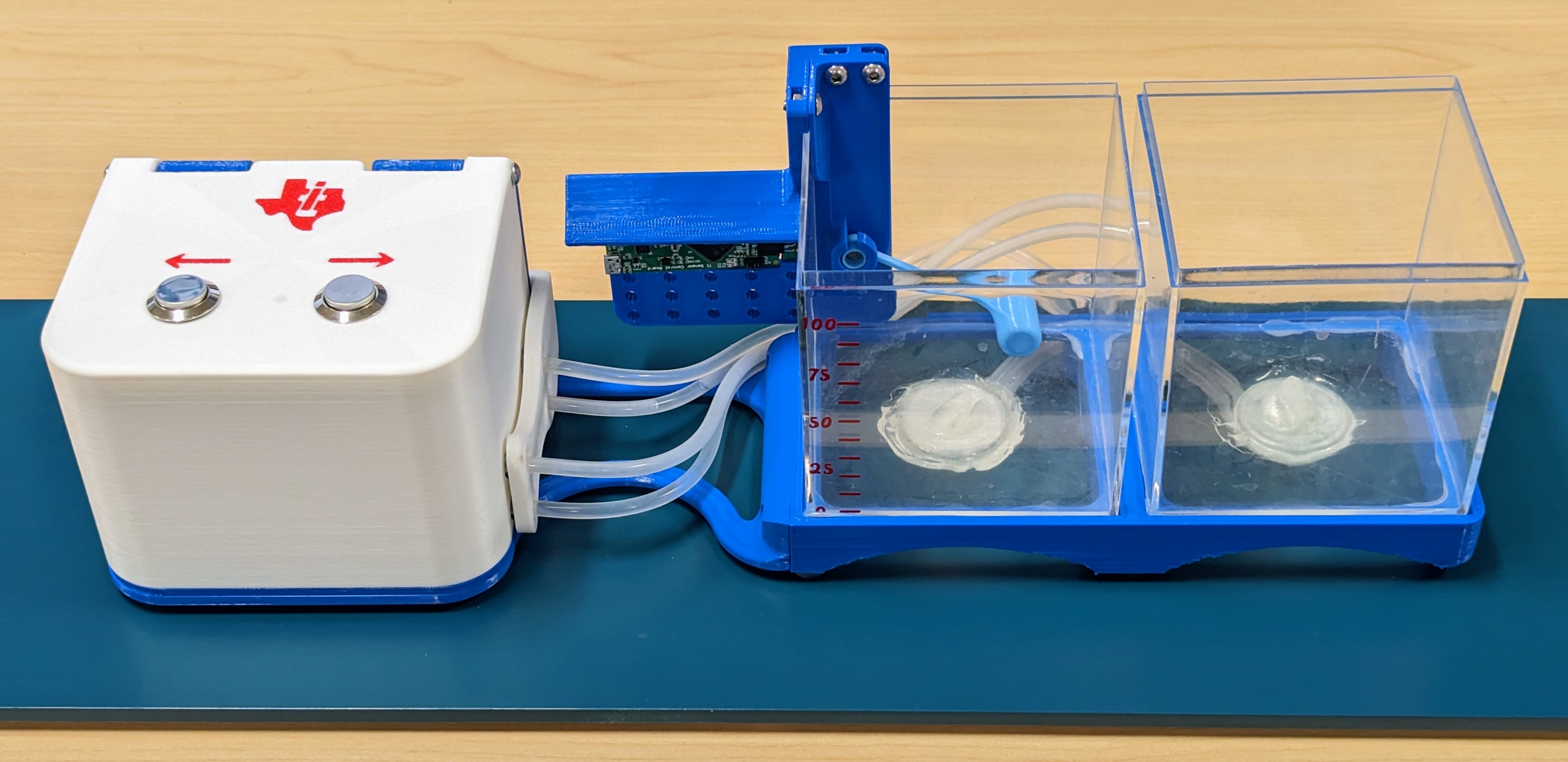
 Figure 3-1 Full Demo Overview
This functional prototype shown in Figure 3-1 was built for demonstrating liquid level sensing using a TMAG5273. The white box on the left houses a DRV8704 motor driver EVM and a pair of pumps that transfer water from one tank to the other. The center water tank has the TI-SCB and TMAG5273EVM along with the float arm and magnet.
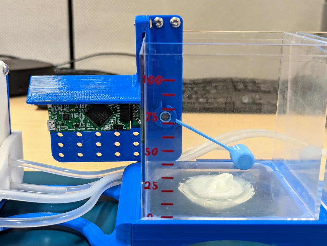
 Figure 3-2 Sensing-Focused Demo
Closeup
Figure 3-2 Sensing-Focused Demo
CloseupA closer view of the sensing part of the demo is shown in Figure 3-2. There is a scale from 0 to 100 taped to front of the tank. The white attachment in the center of the bottom of the tank redirects the water into the corner of the tank instead of shooting vertically out of the container like a fountain.
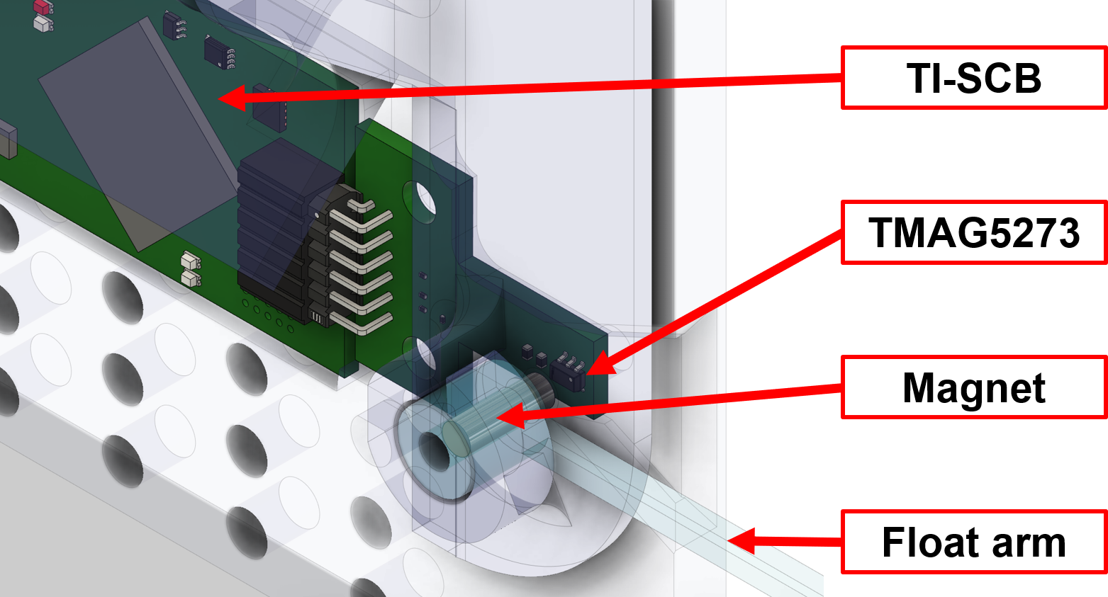
The TMAG5273EVM and TI-SCB are mounted on some 3D printed pieces outside of the water tank as shown in Figure 3-3. Since they are outside of the tank, the electronics do not get wet.
 Figure 3-3 Main Component Locations
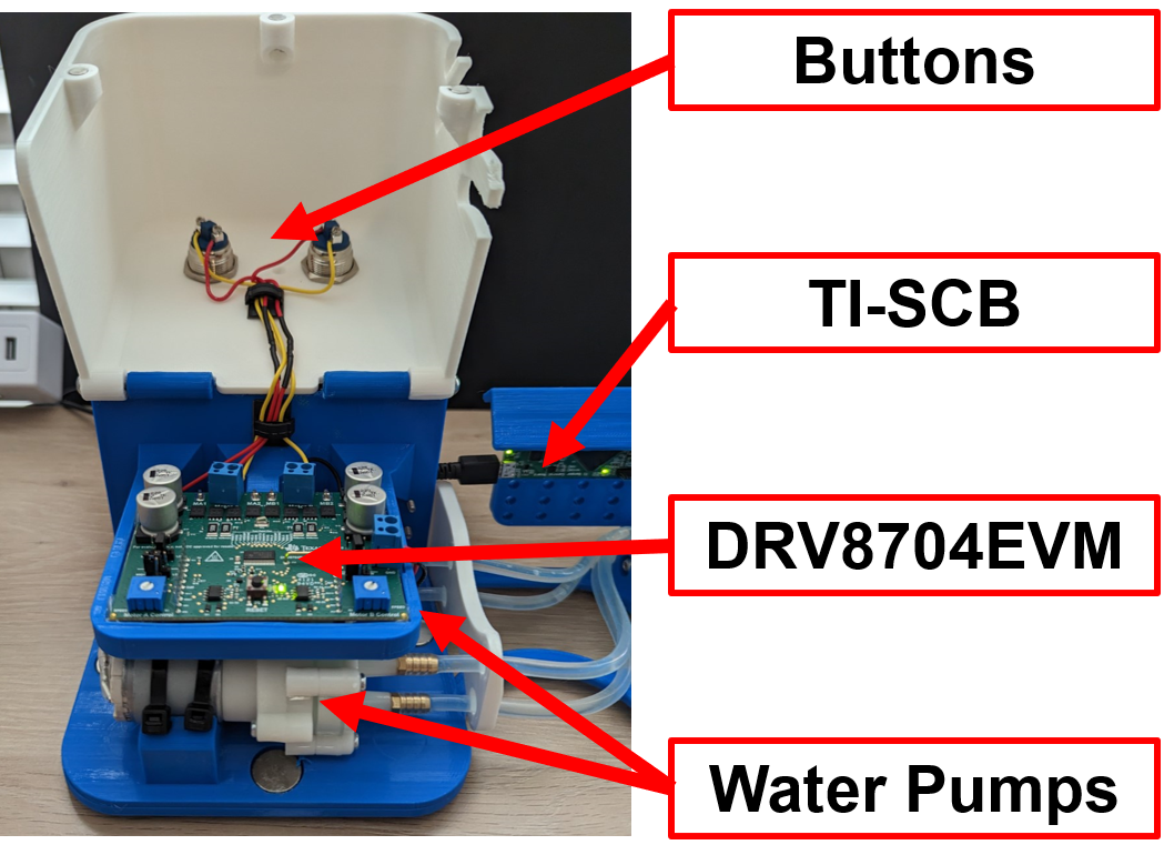
For demonstration purposes, a pair of self-priming pumps was used to transfer water from one tank to the other. One pump moved water from the left tank to the right tank, the other pump moved water from the right tank to the left tank. These pumps were driven by a DRV8704EVM. Though the DRV8704 can run a motor bidirectionally, the pumps can only pump water one direction so the demo uses two pumps instead of one. This pump setup enables the user to add and remove water in the liquid level sensing tank at the press of a button.
 Figure 3-4 Pump Box