SLYA076 july 2023 TMAG5273
3.1 Float Arm
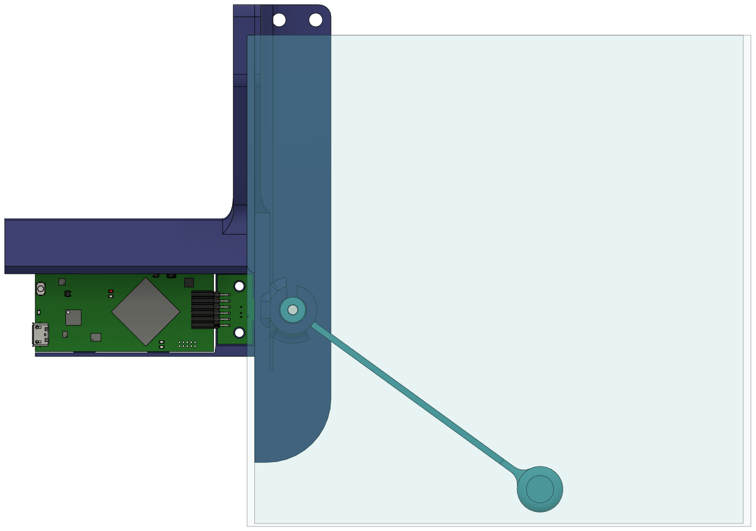
For this application, a diametric magnet must be installed on the float sensor so that it rotates with the float arm movement. As the float rises, the magnet will rotate in one direction, and as the float sinks the magnet will rotate in the other direction. This movement is shown in Figure 3-5.
 Figure 3-5 Float Rotation and Magnet
Placement
Figure 3-5 Float Rotation and Magnet
PlacementThe hall sensor is mounted on the outside of the water container, sensing the magnetic field through the side of the container wall. The size of the magnet will determine the strength of the magnetic field and thus the maximum distance between the magnet and the sensor.
This demo was tested with 3 different float arm models to test 3 different sized diametric cylinder magnets from 1/8", 3/16", and 1/4" diameter as seen in Figure 3-6. All three magnets work with this solution, the field strength is sufficient to accurately track the angle through the water tank wall.
 Figure 3-6 Three Magnet Sizes in Float
Arms
Figure 3-6 Three Magnet Sizes in Float
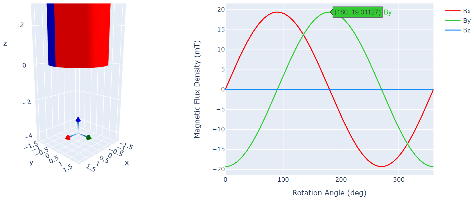
ArmsThe magnets are approximately 4 mm from the surface of the TMAG5273 when the setup is assembled. This results in a max field strength of 19.3 mT with the 1/8 inch magnet (Figure 3-7), and a max of 42.9 mT with the 1/4" magnet. Depending on the accuracy of your 3D prints and assembly, you might need to increase the maximum input setting of the TMAG5273 from 40.0 mT to 80.0 mT. Figure 3-8 shows the result from TI Magnetic Sense Simulator (TIMSS) for the 1/8" diameter magnet at 4.00 mm separation from the sensor. TIMSS can be found at TI-MAGNETIC-SENSE-SIMULATOR.
 Figure 3-7 Magnetic Field Strength Results at
4.0 mm with 1/8 Inch Magnet
 Figure 3-8 TMAG5273 Output Across
360°
Figure 3-8 TMAG5273 Output Across
360°This design can easily be modified to work with many size water tanks. Simply change the length of the float arm and the height of the magnet and sensor. Figure 3-9 shows the demo adapted for a larger water container by using a larger arm and adjusted sensor location. The maximum measurable range will be achieved with the sensor at the middle height of the tank and the float arm just long enough to reach the bottom and top of the tank. With a longer arm, the angle measurement range decreases. For a short arm the range of measurement approaches 180°, but for a long arm if the angle at Empty can be 0° then the angle at Full can only be 45°. Thus, an appropriately shaped flotation arm needs to be designed for the end equipment system.
 Figure 3-9 Adapt Design for Larger Water
Container