SLYA080 july 2023 TMAG5273
3.1 On-Axis Test
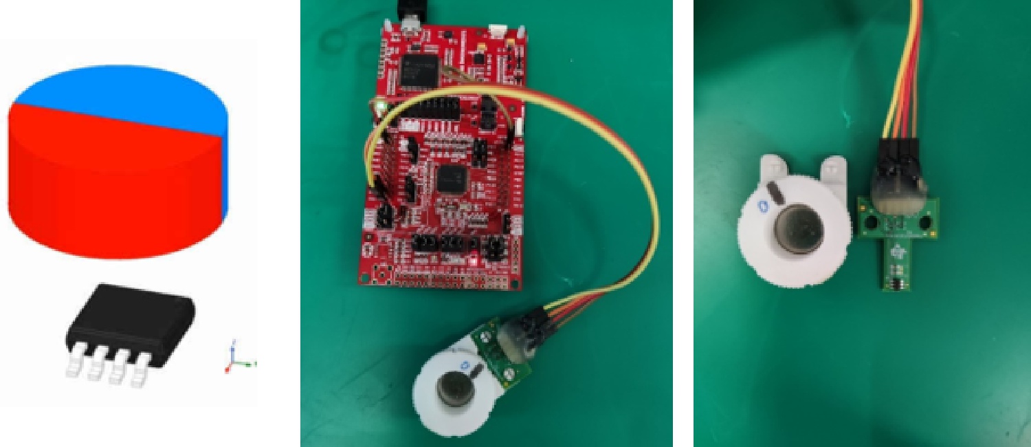
Using the on-axis method, the magnet is placed directly above the sensor. As shown in Figure 3-2, the X and Y axes of the 3D Hall sensor are selected to determine the rotation angle of the magnet.
 Figure 3-2 3D Linear Hall-Effect Sensor
On-Axis Test
Figure 3-2 3D Linear Hall-Effect Sensor
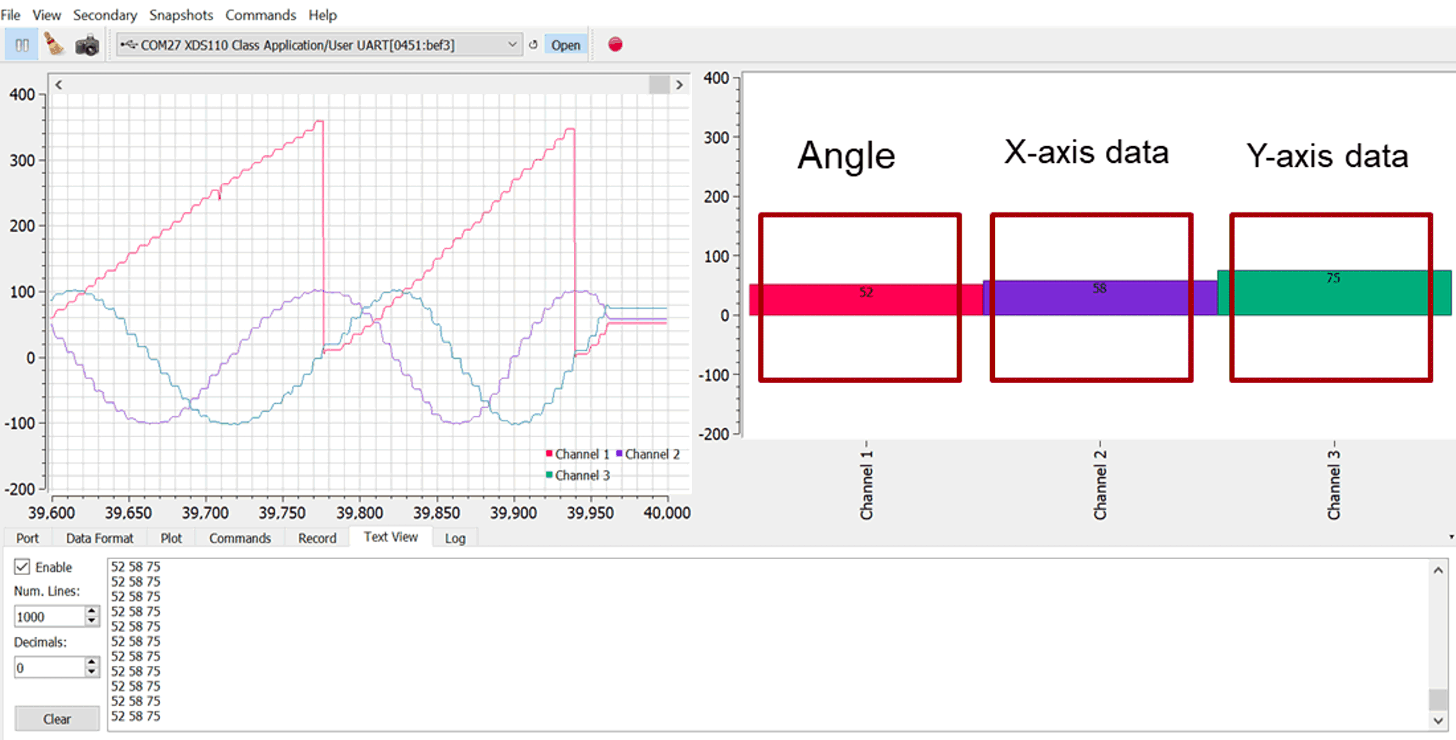
On-Axis TestThe CORDIC engine of the TI 3D Hall sensors TMAG5273 and TMAG5170 calculates the angle seamlessly so the microcontroller can directly read the value of the register without processing the magnetic field data. Figure 3-3 shows the angle data and X and Y axes data in the actual test. Please note that the curve has a stepped shape due to manual turning of the knob.
 Figure 3-3 Angle Data and XY Axes Data
Output
Figure 3-3 Angle Data and XY Axes Data
OutputWhen the magnet rotates, the X and Y axes of the magnetic field change in a sinusoidal mode. See Figure 3-4.
 Figure 3-4 3D Linear Hall-Effect Sensor
On-Axis Output