SLYA085 December 2023 TMAG6180-Q1
1 Introduction
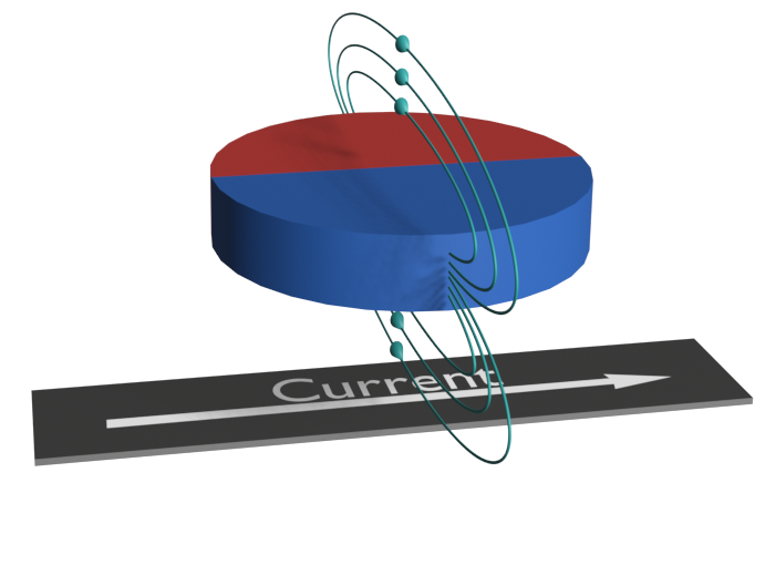
Unlike Hall-effect, Giant Magneto-Resistive (GMR), and Tunneling Magneto-Resistive elements (TMR), the Anisotropic Magneto-Resistive (AMR) sensing element does not have an output voltage proportional to the magnitude of the applied magnetic field in the direction of sensitivity. Rather, the AMR sensing element exhibits a change in resistance regarding the direction of the applied magnetic field vector.
 Figure 1-1 AMR Nominal Impedance
Alignment
 Figure 1-2 AMR Reduced Impedance
Alignment
Figure 1-2 AMR Reduced Impedance
AlignmentFigure 1-1 demonstrates that there is no resulting change in impedance with the magnetic field applied parallel to the flow of current through the sensing element. However, if the applied field is orthogonal to the sensing element then the impedance varies up to a maximal saturation point (Figure 1-2).
For example, suppose that the resistive element is exposed to an oscillating magnetic field, then the resulting behavior of the AMR resistivity follows the expression in Equation 1.
 Figure 1-3 AMR Impedance vs Field Orientation