SLYU058D May 2021 – February 2024 TMAG5173-Q1 , TMAG5273
4.2 Rotate and Push Demo
The TMAG5273EVM comes with the rotate and push 3D print. However, this 3D print can also work with the TMAG5173 since both devices use the same magnetic range. To use the Rotate and Push Demo, follow these steps:
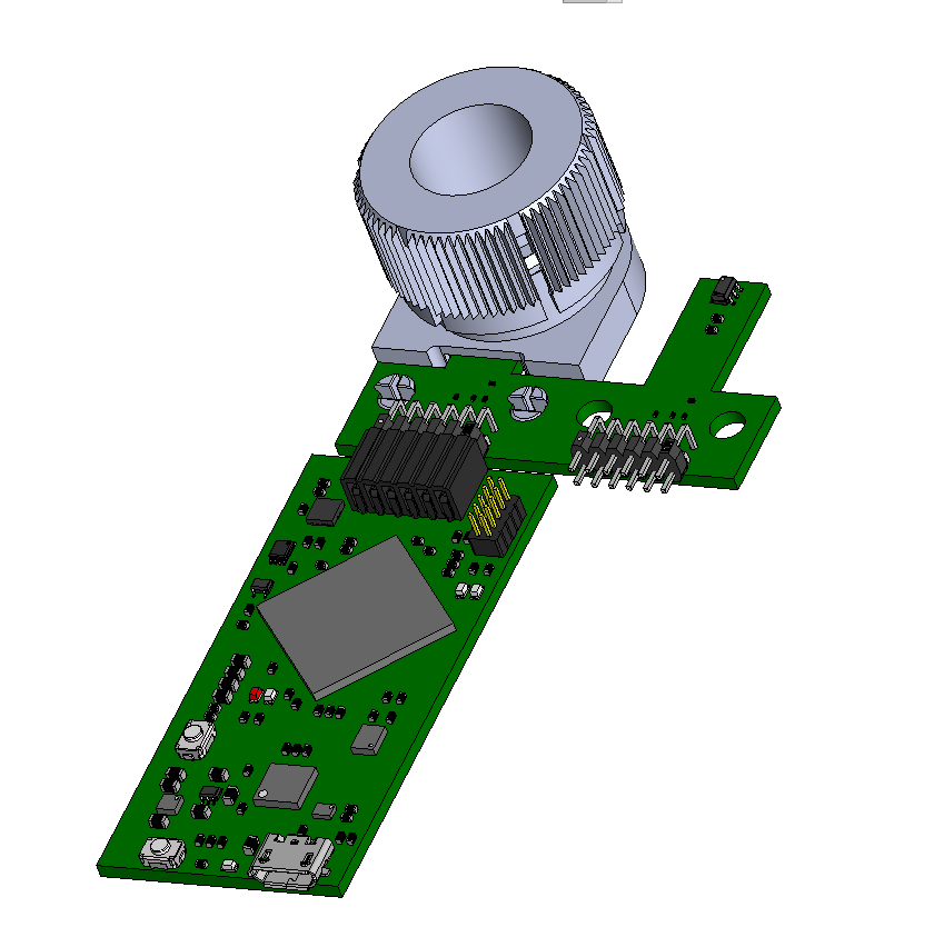
- Attach the Rotate & Push Module to the EVM
(see Figure 4-10 for an example on how this module is connected to the A1 part of the
EVM).
 Figure 4-10 Rotate & Push
Module on EVM
 - In the GUI register page:
- Select the DEVICE_CONFIG2 register and
check the following:
- Make sure the drop-down menu option for the OPERATING_MODE register bits says 00b = Standby Mode
- Make sure the drop-down menu option for the TRIGGER_MODE register bits says 0b=Conversion Start at I2C Command Bits
- Click the SENSOR_CONFIG1 register and select the 0011b= X, Y channel enabled option under the MAG_CH_EN drop-down menu to enable the X and Y channels.
- Click the SENSOR_CONFIG2 register and set
the X_Y_RANGE drop-down menu to one of the below options (note
that the same range option is selected for the X and Y axes; however,
the Z axis range can be set independently of the x and y axes range
setting):
- If the TMAG5273A1 part of the EVM is connected to the SCB, then select the 1b = ±80 mT (TMAG5273x1)/ ±266mT (TMAG5273x2) option. This makes sure that the 80-mT variant is selected for the TMAG5273A1. Note that the demo does not work with the 40-mT range because the magnetic flux density produced by the Rotate and Push Module is greater than 40 mT, which is why the 80-mT range is selected.
- If the TMAG5273A2 part of the EVM is connected to the SCB, then select the 0b = ±40 mT (TMAG5273x1)/ ±133mT (TMAG5273x2) option. This makes sure that the 133-mT range option is selected. The 266 mT can also be used here instead, but the results using this range is not as good as the results with the 133-mT range.
- Optional: Click the SENSOR_CONFIG2 register and set the ANGLE_EN drop-down menu to 01B = X 1ST, y 2ND. Performing this step enables the TMAG5273’s angle measurement calculation.
- Set the Auto Read at the top of the register map to As fast as possible.
- Select the DEVICE_CONFIG2 register and
check the following:
- Go to the Rotate & Push tab inside the
plots page (see Figure 4-11).
 Figure 4-11 Rotate & Push GUI
Page
 - As the user turns the knob on the Rotate &
Push Module, the angle displayed on the dial and text below the dial changes
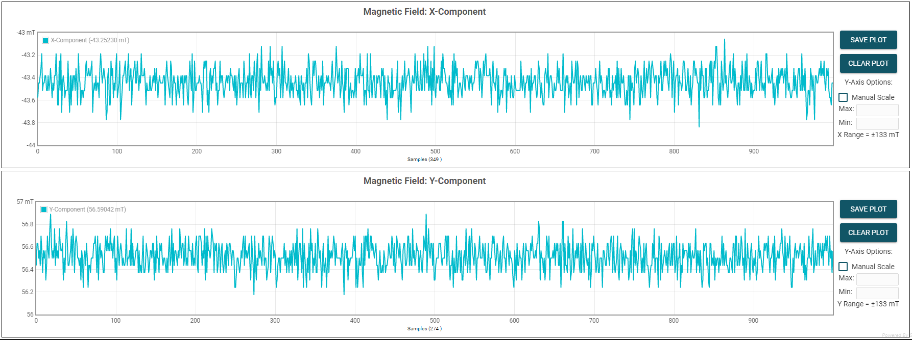
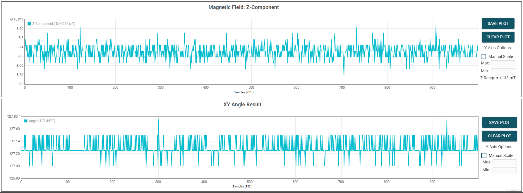
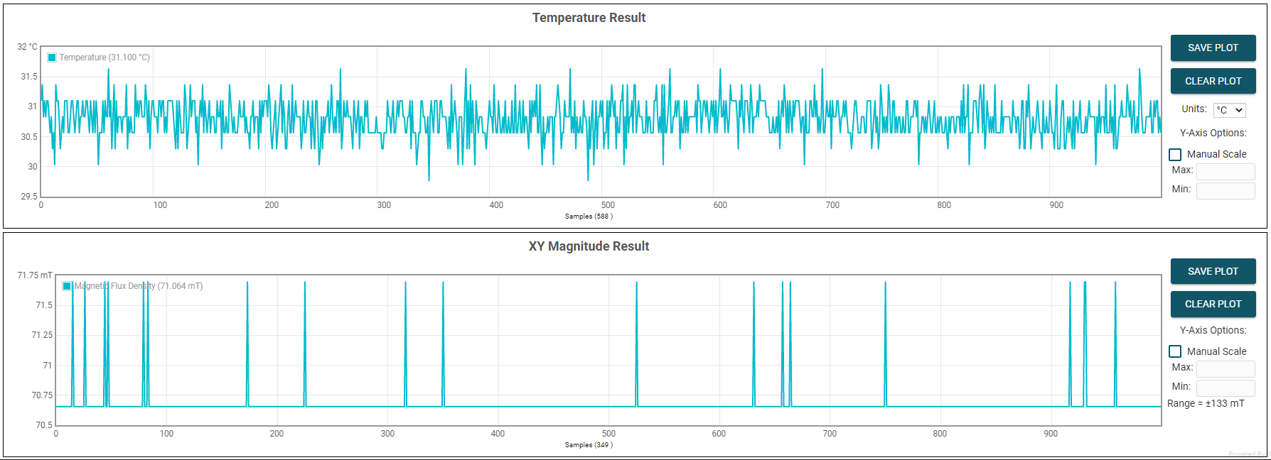
accordingly. Click the Plots tab to see the resulting X and Y channel
waveforms (Figure 4-12), device angle measurement (Figure 4-13), and magnitude (Figure 4-14) during this process.
 Figure 4-12 X and Y Channel GUI
Plots
 Figure 4-13 Device's Angle
Measurement Plot
 Figure 4-14 Device's Magnitude
Plot
 - Press the STOP COLLECT button to stop collecting data.
- After testing a particular TMAG5x73 device variant, make sure to first disconnect the SCB USB cable from the PC before connecting the SCB to another part of the EVM board associated with the other TMAG5x73 device variant. After disconnecting the cable, the part of the EVM board associated with the other TMAG5x73 variant must be connected to the SCB before reconnecting the SCB USB cable to the PC.