SNAU257 October   2020 TPL1401


  1.   Trademarks
  2. 1Overview
    1. 1.1 Kit Contents
    2. 1.2 Related Documentation from Texas Instruments
  3. 2System Setup
    1. 2.1 Software Setup
      1. 2.1.1 Operating Systems
      2. 2.1.2 Software Installation
      3. 2.1.3 Analog EVM Controller Firmware Upgrade
    2. 2.2 Hardware Setup
      1. 2.2.1 Power Configurations and Jumper Settings
      2. 2.2.2 Connecting the Hardware
      3. 2.2.3 Electrostatic Discharge Warning
  4. 3Detailed Description
    1. 3.1 Hardware Description
      1. 3.1.1 Theory of Operation for the BOOSTXL-DAC-PORT
      2. 3.1.2 Signal Definition of the BOOSTXL-DAC-PORT
      3. 3.1.3 Theory of Operation for the TPL1401EVM Hardware
      4. 3.1.4 Signal Definition of the TPL1401EVM
    2. 3.2 Software Description
      1. 3.2.1 Starting the Software
      2. 3.2.2 Software Features
        1. 3.2.2.1 Home Page
        2. 3.2.2.2 Setup Page
        3. 3.2.2.3 DIGIPOT Quick-Start Page
          1. 3.2.2.3.1 Basic DPOT Configuration Tab
        4. 3.2.2.4 Register Map Page
        5. 3.2.2.5 Collateral Page
  5. 4Schematic, PCB Layout, and Bill of Materials
    1. 4.1 BOOSTXL-DAC-PORT Schematic
    2. 4.2 TPL1401EVM Schematic
    3. 4.3 PCB Components Layout
    4. 4.4 BOOSTXL-DAC-PORT Bill of Materials
    5. 4.5 TPL1401EVM Bill of Materials
Basic DPOT Configuration Tab

Figure 3-7 shows the Basic DPOT setup tab that provides an interface to quickly power up, select the reference and output span, and program the output voltage (decimal) for the TPL1401. The TPL1401 comes in Hi-Z power-down mode by default.

Note:

The basic DAC setup for power up, reference selection, and output span selection available in this tab is common to all the tab functions.

The EEPROM PROGRAM button is used to write the latest register settings to the EEPROM. The RELOAD button is used to retrieve the settings stored in the EEPROM. The A0 pin programming has not been provided in this version of the software, although the hardware has options for all four possible configurations.
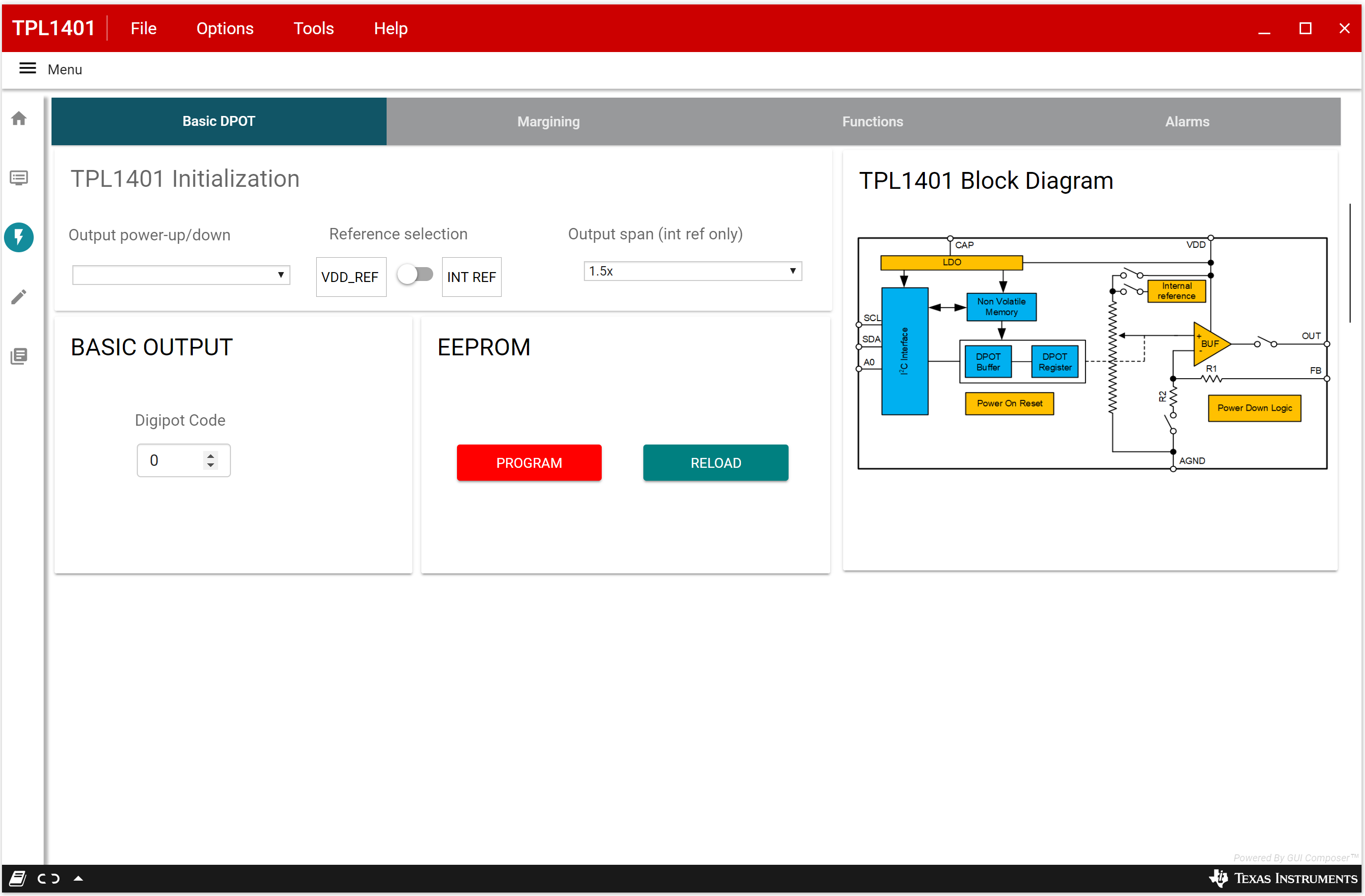
GUID-20200921-CA0I-DVPZ-FJ9X-RZZRQ14N6RGK-low.pngFigure 3-7 TPL1401EVM Quick-Start Page : Basic DPOT Configuration