SNLA446 November 2024 DS320PR410
2 Configuration Page
The following section describes features of the Configuration Page in the DS320PR410 GUI and configuration of the GUI to program the DS320PR410.. This page is used to set up the GUI for correct device communication over SMBus/I2C.
- Launch the SigCon Architect EVM GUI v3 application.
- Click the Configuration
tab below the DS320PR410 profile on the left side of the GUI, as shown in Figure 2-1.
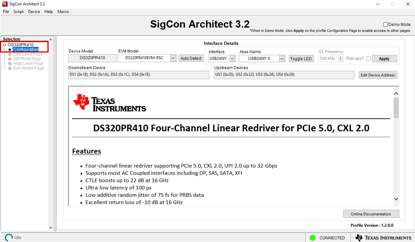
Figure 2-1 DS320PR410 Configuration Page - Click the Auto Detect
button to detect the connected device's SMBus/I2C addresses as shown
in Figure 2-2. As needed, select the Edit Device Address button to manually edit the
assigned Downstream and Upstream device addresses.
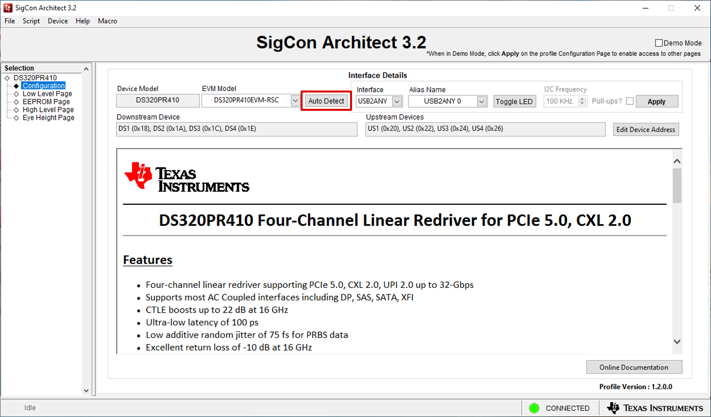
Figure 2-2 SMBus Address Auto Detect - Select the correct interface
adapter below the Interface drop-down menu (USB2ANY or Aardvark). After
selecting the correct interface adapter, click Apply to connect to the
selected DS320PR410 devices. As shown in Figure 2-3, if the correct interface adapter is selected and the SMBus
addresses are configured correctly, the status indicator in the bottom-left
corner of the GUI shows a green LED and the text Connected. After
successful connection, the other tabs under the DS320PR410 profile become
available for selection. Click the desired tab on the left side of the GUI to
begin programming the device / devices.
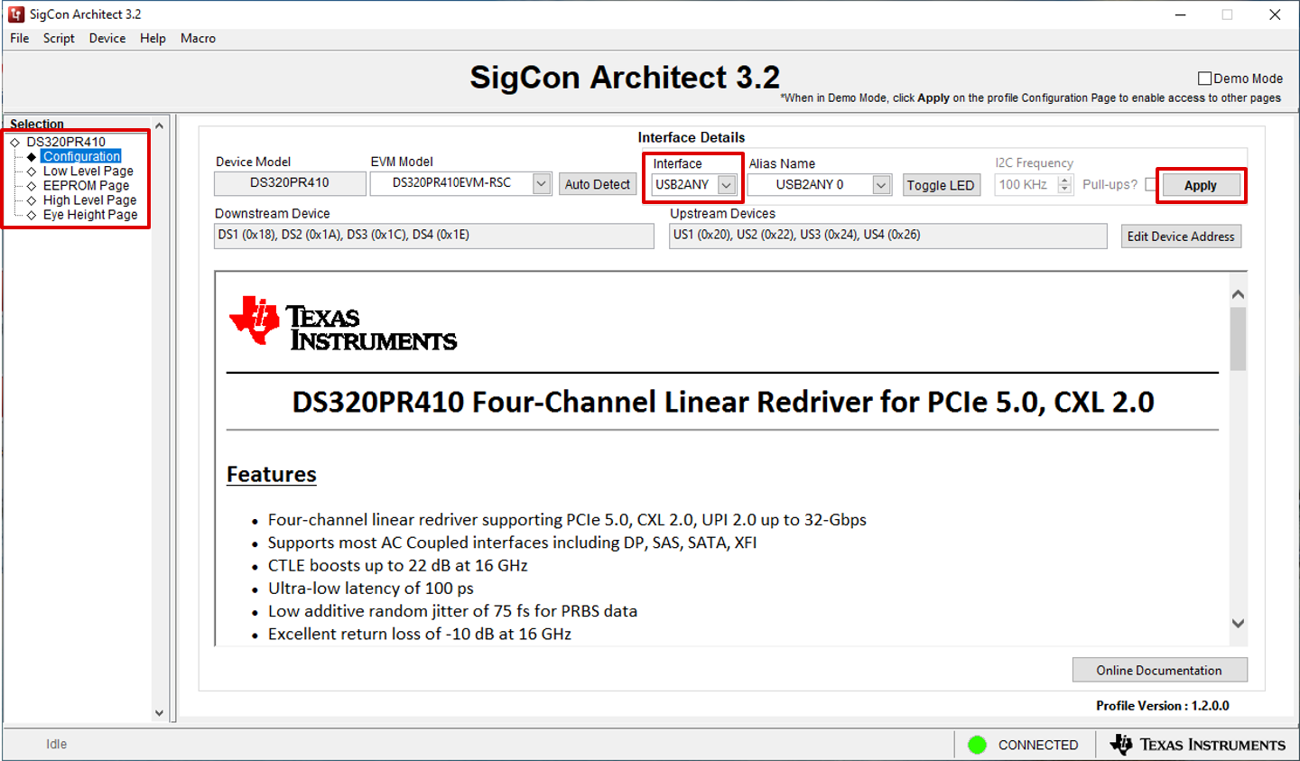
Figure 2-3 Interface Adapter Select and Apply Settings - By default, the GUI is configured
to communicate with the DS320PR410-RSC-EVM evaluation module, which contains 8
DS320PR410 devices (4 facing Downstream, 4 facing Upstream). However, the
DS320PR410 GUI also allows for support of between 1 and 16 DS320PR410 devices
using the EVM Model drop-down menu to select the
DS320PR410EVM-CUSTOM model, shown in Figure 2-4.Using the Edit Device Address button, the desired number of Downstream and Upstream DS320PR410 devices for GUI configuration can be selected, as shown in Figure 2-5. After selecting the desired device counts and the SMBus addresses, press the OK button. Then, click Apply to apply the edited configuration to the GUI.
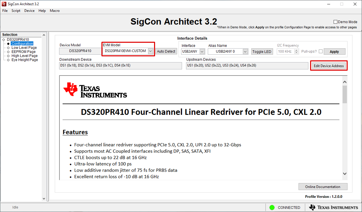
Figure 2-4 DS320PR410EVM-CUSTOM Configuration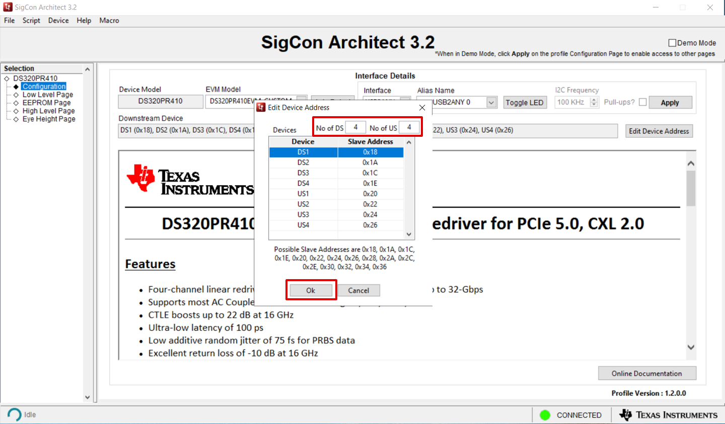
Figure 2-5 DS320PR410EVM-CUSTOM Edit Device AddressNote: Downstream and Upstream device addresses are assigned in increasing sequenial numeric order and can be manually edited to reflect orientation of the redrivers in the system.
Optionally, general GUI functionality can be explored in Demo Mode, which can be selected using the check-box in the upper-right corner of the GUI. When in Demo Mode, the GUI does not attempt to communicate to any device over an interface adapter. Figure 2-6 shows an example of the DS320PR410 GUI in Demo Mode. where the status indicator in the bottom right corner indicates a red LED and the text Demo Mode. To access all pages of the GUI in Demo Mode, click the Apply button.
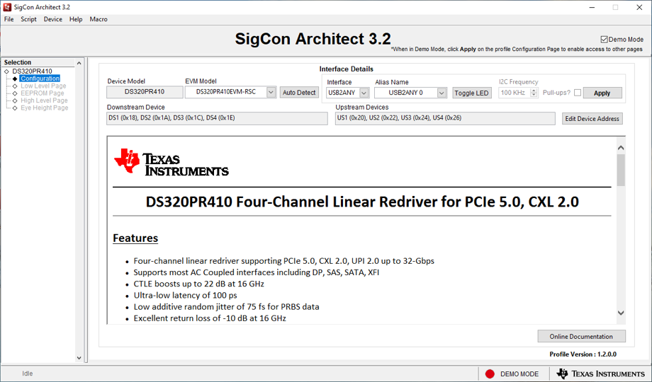
Figure 2-6 DS320PR410 GUI Demo Mode