SNLA446 November 2024 DS320PR410
4 EEPROM Page
The SigCon Architect GUI's DS320PR410 profile can be used to generate an EEPROM file in Intel™ Hex format for a single redriver or multiple DS320PR410 redrivers. When the DS320PR410 is configured in SMBus/I2C primary mode (MODE = L1), the redriver loads the settings stored in an external EEPROM upon power-up. The user can configure those settings using the EEPROM Page. The following section provides an example of how to navigate the DS320PR410 GUI EEPROM Page and create an EEPROM hex file.
In this example, eight DS320PR410 redrivers are present. EQ Index 2 is selected for devices at addresses 0x18, 0x1A, 0x1C, 0x1E and EQ Index 5 is selected for devices at addresses 0x20, 0x22, 0x24, 0x26) For each device, the same value is used for every channel. For programming fewer or additional devices, decrease or increase the number of devices (No. of Devices) and configurations (No. of Configs) as needed.
- Multiple devices can be programmed at once.
Select the number of devices and the number of configurations using the menus
shown in Figure 4-1. Up to 32 different configurations can be created and assigned to each device
and channel, if desired.
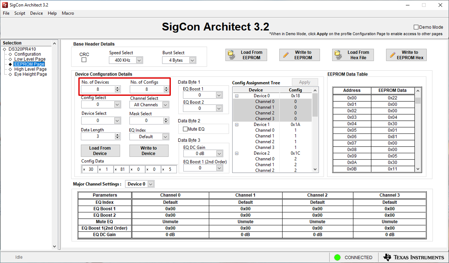
Figure 4-1 EEPROM Page: Number of Configs and Number of Devices - To program the first
device, select Configuration 0 and Device 0 from the respective drop-down menus,
Config Select and Device Select. Note the Config Assignment
Tree shows the hex address of each device (0x18 for Device 0). Verify
that the Data Length is set to 3, as 3 bytes of data are needed to
program the DS320PR410. Each of these menus are shown in Figure 4-2.
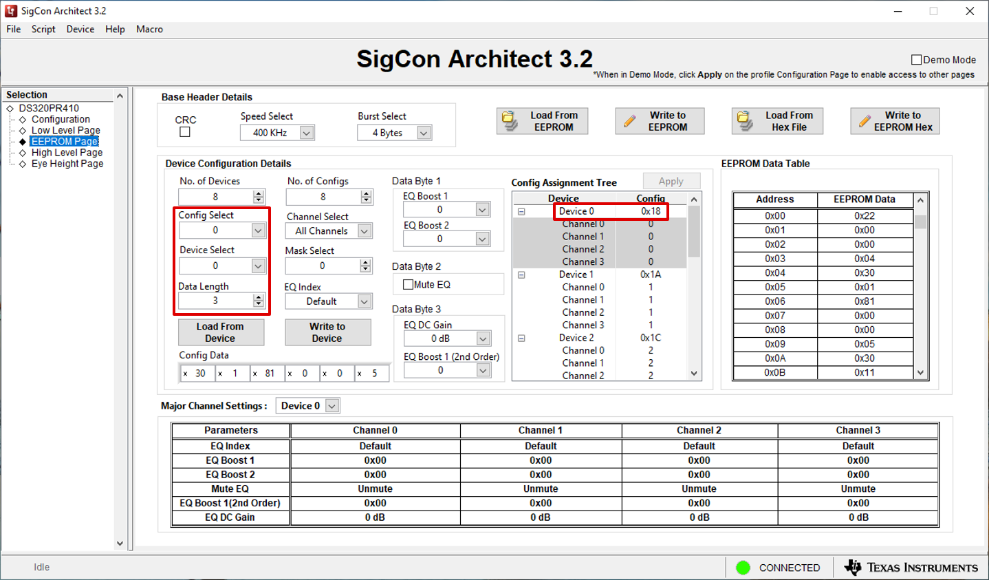
Figure 4-2 EEPROM Page: Config Select, Device Select, and Configuration Assignment Tree - To select the desired channel or channels, choose
an EQ Index from the drop-down menu. The EQ Index drop-down
automatically adjusts the EQ Boost 1, EQ Boost 2, and EQ Boost
1 (2nd Order) fields. Select the desired EQ DC Gain. Note in the
Config Assignment Tree that the channels of Device 0 selected using
the Channel Selectdrop-down menu are configured using Configuration 0.
Continue this process for each Device and Configuration, selecting
the appropriate EQ Index and EQ DC Gain for each. Each of these
drop-down menus are shown in Figure 4-3.
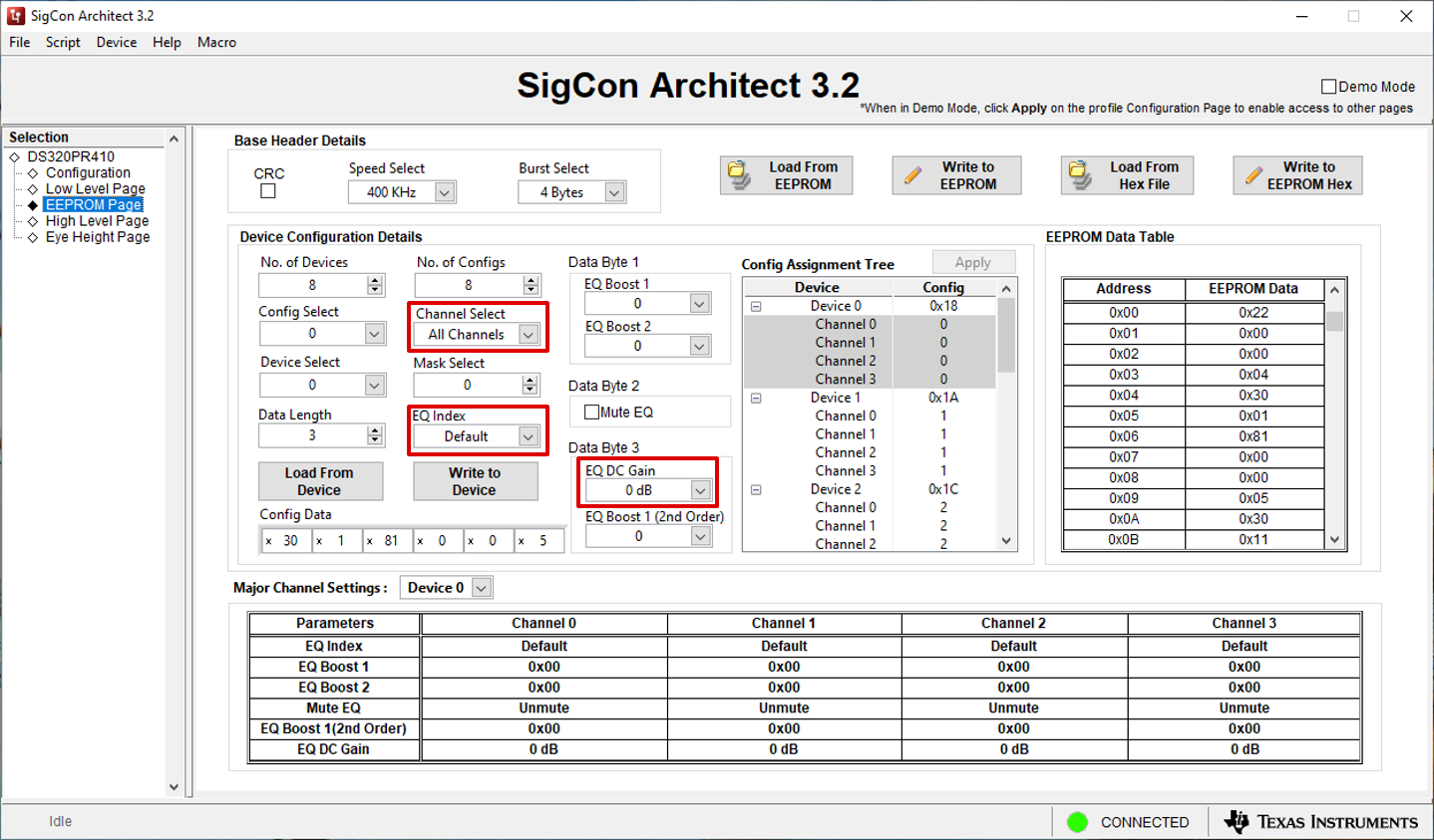
Figure 4-3 EEPROM Page: Channel Select, EQ Index, and EQ DC GainOptionally, the Major Channel Settings table can be used to check each device's EQ settings. The device drop-down menu can be used to select the desired device for viewing as shown in Figure 4-4.
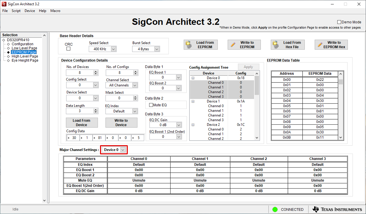
Figure 4-4 EEPROM Page: Major Channel Settings - After all devices have been configured, click the
Write to EEPROM button to write the external EEPROM with the new
settings. The button indicator turns green when the write is completed, as shown
in Figure 4-5.
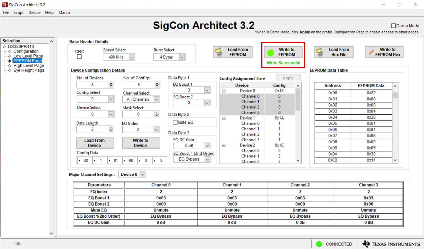
Figure 4-5 EEPROM Page: Write to EEPROM - To save the current EEPROM settings configured using the GUI into a hex file, click the Write to EEPROM Hex button shown in Figure 4-6 to write a hex file with these settings. Save the hex file to any desired location using the File Explorer.
- To load EEPROM settings back into the GUI from a hex file, click the Load from Hex File button. Select the desired hex file to load from the File Explorer. If the user desires to write these settings to an external EEPROM connected to the accessed SMBus lines, click the Write to EEPROM button and wait for the green Write Successful indicator to appear to indicate a successful EEPROM write.
- To load EEPROM settings into the
GUI from an external EEPROM connected to the accessed SMBus lines, click the
Load from EEPROM button.
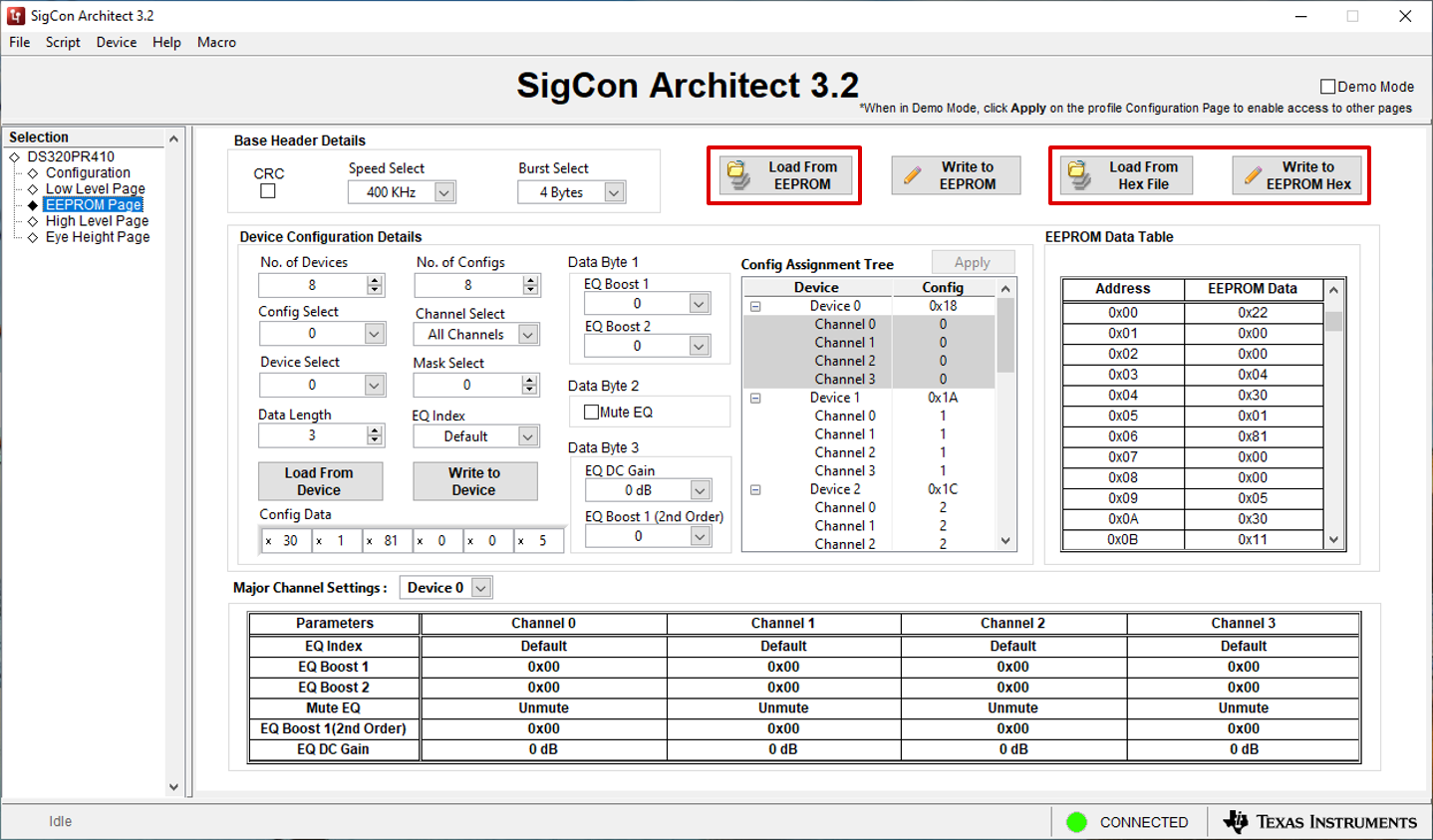
Figure 4-6 EEPROM Page: Load from EEPROM, Load from Hex File, Write to EEPROM Hex