SNLA446 November 2024 DS320PR410
5 High Level Page
The DS320PR410 redriver features a continuous-time linear equalizer (CTLE) that applies high-frequency boost and low-frequency attenuation to help equalize the frequency-dependent insertion loss effects of a passive channel. CTLE settings are referred to as EQ settings in this section for clarity and brevity.
The High Level Page is used to quickly and easily adjust the EQ settings as needed for your specific application. A further description of the EQ settings can be found in the DS320PR410 Four-Channel Linear Redriver for PCIe™ 5.0, CXL 2.0, data sheet. The page contains a Device Status tab to monitor each connected device's channel status and a Block Diagram tab to adjust the EQ settings of each connected device. The following steps walk through the features of the detailed features of the High Level Page.
- After clicking on the High Level Page tab
on the left side of the GUI, the Device Status tab is shown, such as in
Figure 5-1. Each channel status is updated sequentially, showing each
connected device's channel RX Detect and EEPROM Bank Load status, along with the
channel's current EQ settings. The RX Detect status bar appears green if proper
receiver impedance detection is found and red if proper receiver impedance
detection is not found. EEPROM Load status bars appear green if the device's
register bank has properly loaded EEPROM data and red if EEPROM data has failed
to load. Note that the EEPROM Load status always indicates a failed (red) load
status when the device is operating in SMBus/I2C secondary mode (MODE
= L2). The current EQ settings are shown to the right of each channel's status
indicators.
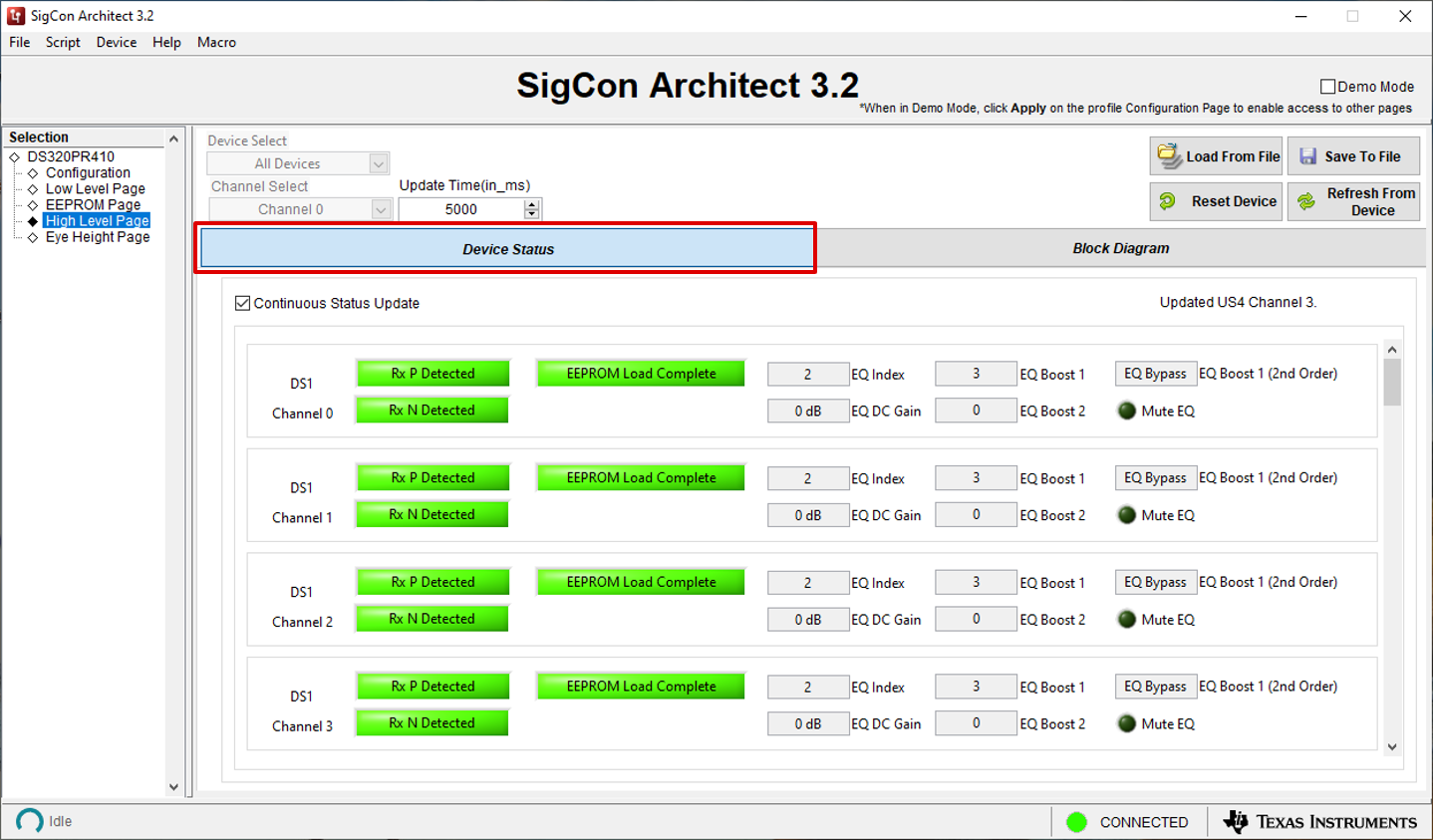
Figure 5-1 High Level Page: Device Status Tab - Click the Block
Diagram tab to show the screen highlighted in Figure 5-2. Here, the EQ settings (EQ Index, EQ Boosts, EQ DC Gain) for
each channel can be adjusted. To program the settings for a specific device or
channel, select a device and channel from the respective Device Select
and Channel Select drop-down menus.
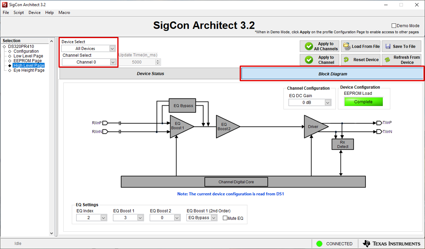
Figure 5-2 High Level Page: Block Diagram Tab, Device and Channel Select - Select the desired EQ Index / EQ Boost
settings and EQ DC Gain. The EQ Index drop-down menu is the
easiest way to quickly adjust the amount of redriver equalization boost applied.
After selecting an EQ Index value, the EQ Boost 1, EQ Boost
2, and EQ Boost 1 (2nd order) fields are automatically populated.
The user can adjust each boost value for finer tuning as needed. Refer to the
device data sheet for more information regarding EQ Index boost values.
These options are highlighted in Figure 5-3.
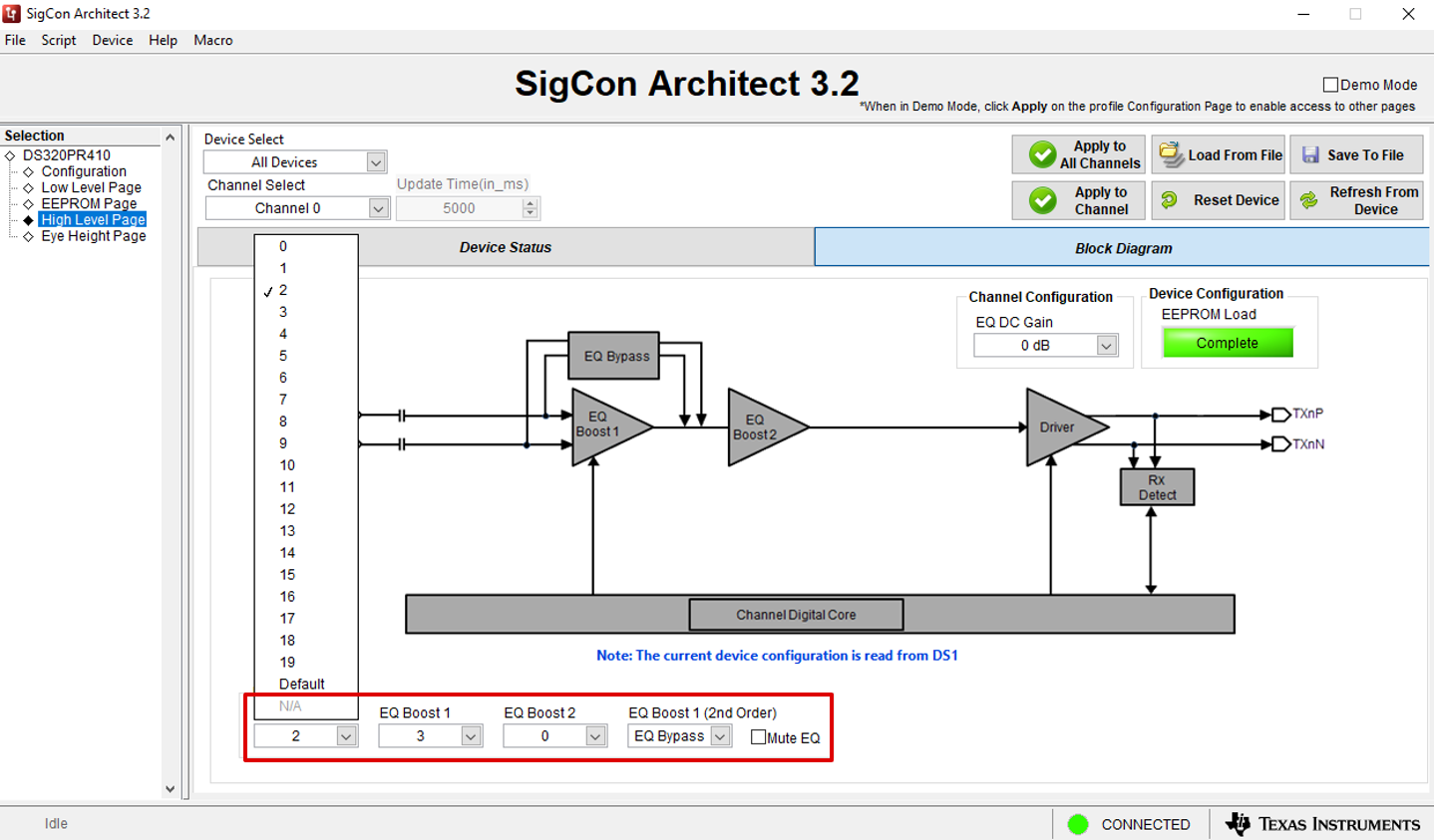
Figure 5-3 High Level Page: EQ Index and EQ Boost SelectThe EQ DC Gain drop-down menu highlighted in Figure 5-4 can be used to adjust channel DC Gain (Flat Gain). Further information regarding DC Gain can be found in the device data sheet. The EQ DC Gain value of 0dB is recommended for most applications.
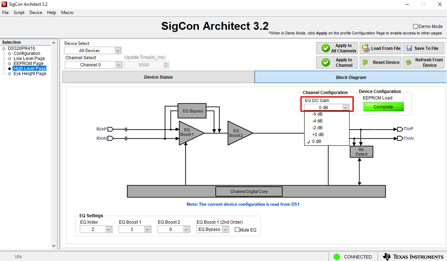
Figure 5-4 High Level Page: EQ DC Gain SelectClick the Apply to Channel button to apply the selected EQ settings to the selected Device and selected Channel (indicated by the Device Select and Channel Select drop-down menus, respectively). Click the Apply to All Channel button to apply selected EQ settings to all channels of the device or devices selected using the Device Select drop-down menu. These options are highlighted in Figure 5-5.
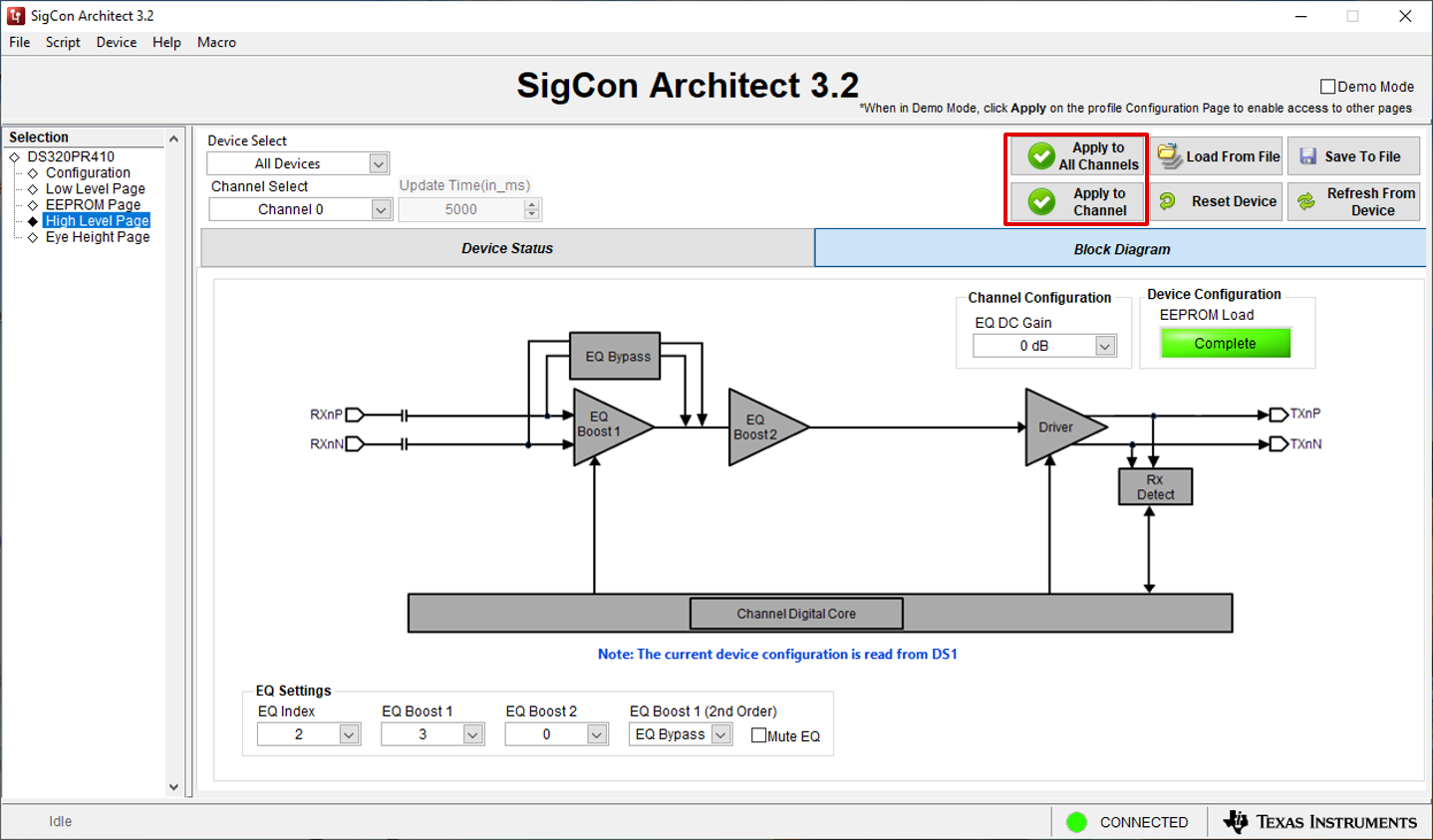
Figure 5-5 High Level Page: Apply to Channel and Apply to All Channels