SNLU343 June 2024 DP83TD510E
2.1 Quick Setup
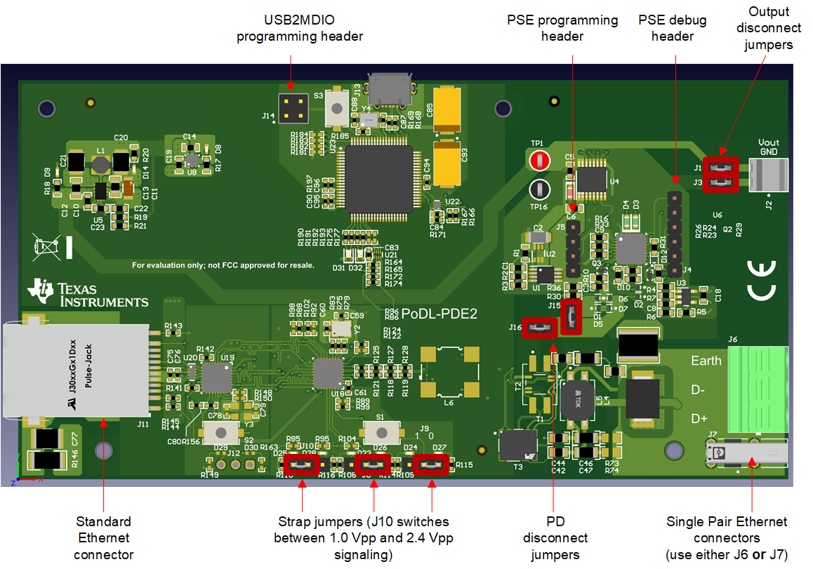
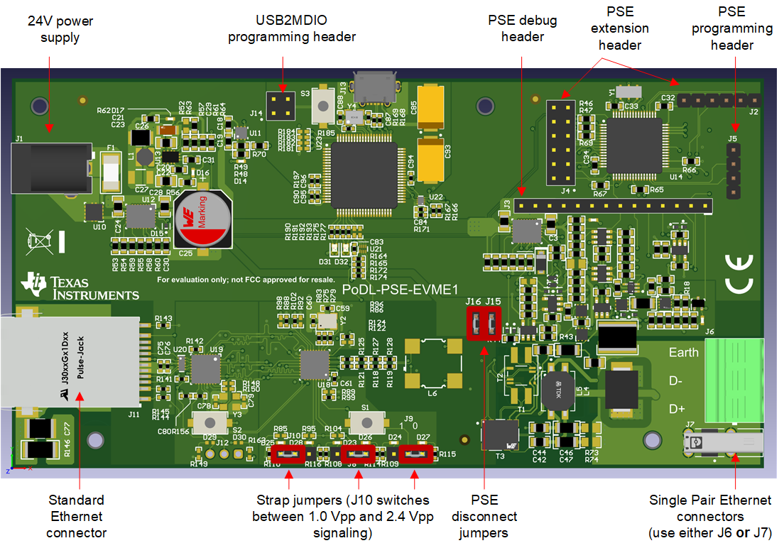
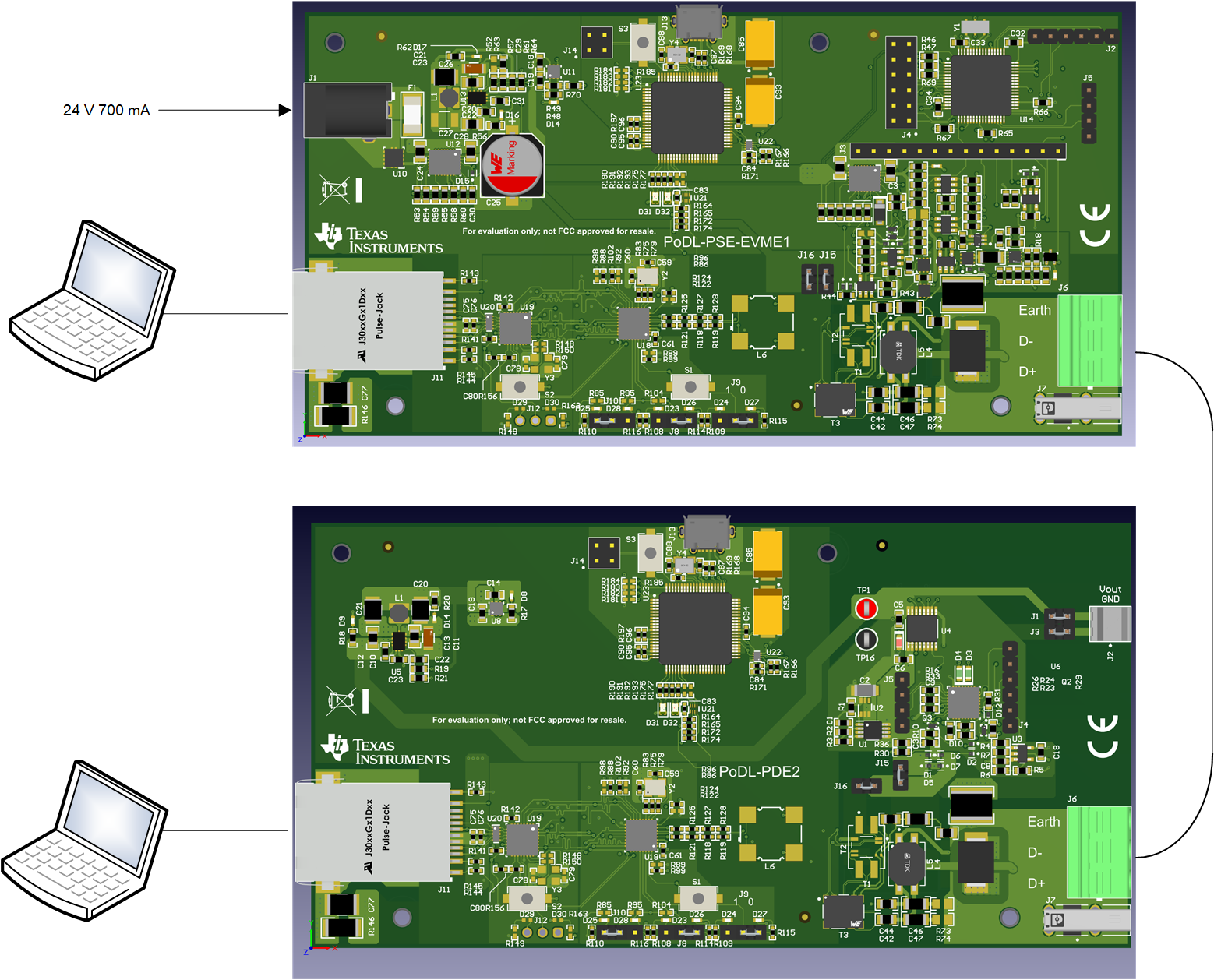
Connect SPE ports of both boards together by either using a SPE cable and the SPE connector J7, or by using a appropriate cable and the screw terminal J6. Verify the jumper settings are as shown below. The PSE needs to be connected to a 24 V power supply. For class 12 operation, the PSE needs to provide at least 700 mA. Figure 3-2 shows how the jumper have to be set for correct operation and explains the connections. Similar on the PD side, Figure 3-1 shows the connections and settings.
 Figure 2-1 PD Jumpers
 Figure 2-2 PSE Jumpers
Figure 3-3 shows how both boards have to be connected. For the SPE cable, make sure to connect D+ and D-, the polarity is not critical. If a shielded cable is used, then also connect the shield.
 Figure 2-3 Board Connections