SNOA963B February 2020 – July 2021 LDC2112 , LDC2114 , LDC3114 , LDC3114-Q1
3 Threshold Configuration Process
Tuning button sensitivity requires a correctly configured LDC211x/LDC3114. The configuration process(3) prior to tuning the button activation force should include the following:
- Selecting the correct power mode (LPWRB pin)
- Choosing the appropriate scan rate (NP_SCAN_RATE, LP_SCAN_RATE)
- Setting the correct sensor configuration (SENSORn_CONFIG)
- Configuring the counter-scale value (CNTSC)
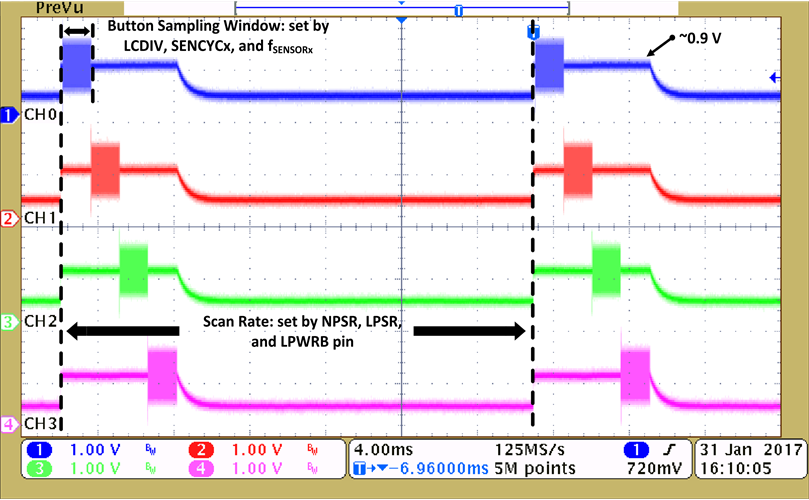
A quick way to check whether the device is configured correctly is by probing the INx pins; the waveforms should resemble those shown in Figure 3-1.
 Figure 3-1 INx Waveforms
An error-free STATUS (Register 0x00) and correct sensor frequency, sampling window, and scan rate are good indications of a correctly configured LDC211x/LDC3114. Once the device has been verified to have been configured correctly the gain can be adjusted for each individual button by following these steps:
- Perform an I2C read transaction to determine the currently programmed GAINn (Registers 0x0E, 0x10, 0x12, and 0x13) and HYST (Register 0x18) values.
- Correlate the GAINn register values to the gain factor by using Table 41 in the LDC2114 data sheet or Table 7-54 in the LDC3114 data sheet. This currently programmed GAINn factor will be referred to as GAINnFACTOROLD from here on.
- Apply the desired amount of activation force on the button being calibrated and perform I2C read transactions to capture the STATUS (address 0x00) and DATAn value for the corresponding button. Using the captured DATAn value the new GAINn factor value can be calculated using Equation 1.

The SWITCHINGTHRESHOLD can be calculated using Equation 2.

where
- HYST is the value stored in register 0x18, which by default is 8
The GAINnFACTORNEW needs to be now correlated back to the closest GAINn decimal value using Table 41 in the LDC2114 data sheet and programmed into the corresponding GAINn register.
If the above process was followed correctly the button should now be calibrated to the desired button activation force. As an additional quality check, one can program the LDC211x/LDC3114 with the calculated gain factor, apply the desired button activation force, and verify if the button turns on. Section 4 walks through an example of the threshold configuration process for an inductive touch button interface.