SNOA993A June 2018 – July 2021 LDC2112 , LDC2114 , LDC3114 , LDC3114-Q1
5.1 Baseline Increment
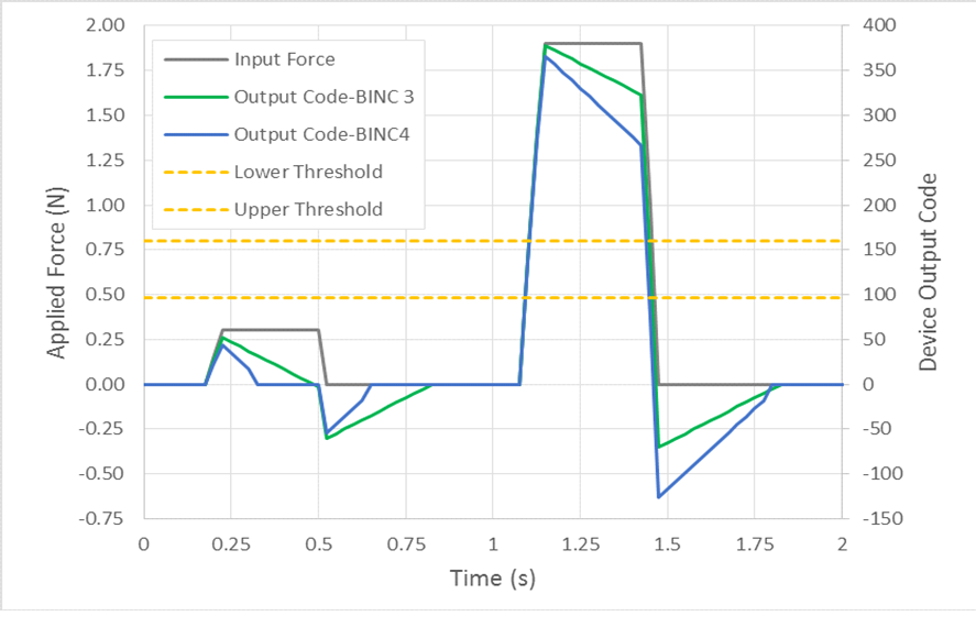
Button detection applications can be effectively implemented by looking at a high-pass filtered version of the input signal, due to the typical stimuli. Refer to Figure 5-1. In the LDC211x and LCD3114 devices, this high-pass filtering is implemented using a subtracted baseline tracking which outputs the shift from the nominal code. This baseline tracking is designed to ignore slow changes in the output code, as these are generally due to environmental shifts which occur over the span of seconds, while a user interaction typically occurs on the order of 50 ms.
The LDC211x and LDC3114 use a linear offset approach, which always drives the output code towards 0.
 Figure 5-1 Baseline Increment produces a decaying output code
Each channel of the LDC211x has its own Baseline value, but the baseline increment is the same for all channels. The internal baseline setting of the LDC211x and LDC3114 is updated for each sample, using the following pseudo-code:
If raw_data[channel] > baseline[channel] then
baseline[channel] = baseline[channel] + base_increment
iIf raw_data[channel] < baseline[channel] then
baseline[channel] = baseline[channel] - base_increment
The net code is then calculated from the raw code with:
net[channel] = raw_data[channel] - baseline[channel]
Where the net code is the output code of the device. Note that this net value will be scaled by the Gain_Factorx and modified by other algorithms before storage in the output register. The baseline increment value can be adjusted across a range of 1 to 128, in 8 settings. A higher setting will bring the output code to 0 in less samples, as displayed in Figure 5-2.
 Figure 5-2 Effect of different values of Baseline Increment
The baseline value is reset whenever the device changes modes (e.g. from Config Mode to Low Power Mode, or from Low Power Mode to normal power mode). Note that baseline tracking is applied for every sample. Faster sample rates have an effectively higher baseline tracking rate per unit time. The Baseline Increment for Normal Power Mode is:
Baseline Increment per Sample = Gain_Factorx × 1.827 ÷ 2(7-NPBI)
Where:
• Gain_Factorx is the linear gain value selected for the channel based on the GAINx field setting, and
• NPBI is the value programmed into the NPBI field
To compensate for the slower sampling interval used in low power mode, the Low Power mode Baseline Increment is effectively 8x larger for the same setting:
Baseline Increment per Sample(Low Power Mode) = Gain_Factorx × 1.827 ÷ 2(4-LPBI)
Where:
• Gain_Factorx is the linear gain value selected for the channel based on the GAINx field setting, and
• LPBI is the value programmed into the LPBI field
The effective Baseline Increment in either mode is not restricted to an integer value, as the LDC2114 has higher internal resolution than is represented by the output code.