SNOAAA7 April 2024 LMG3522R030
3.2 AC Voltage Sampling and True RMS Value Calculation
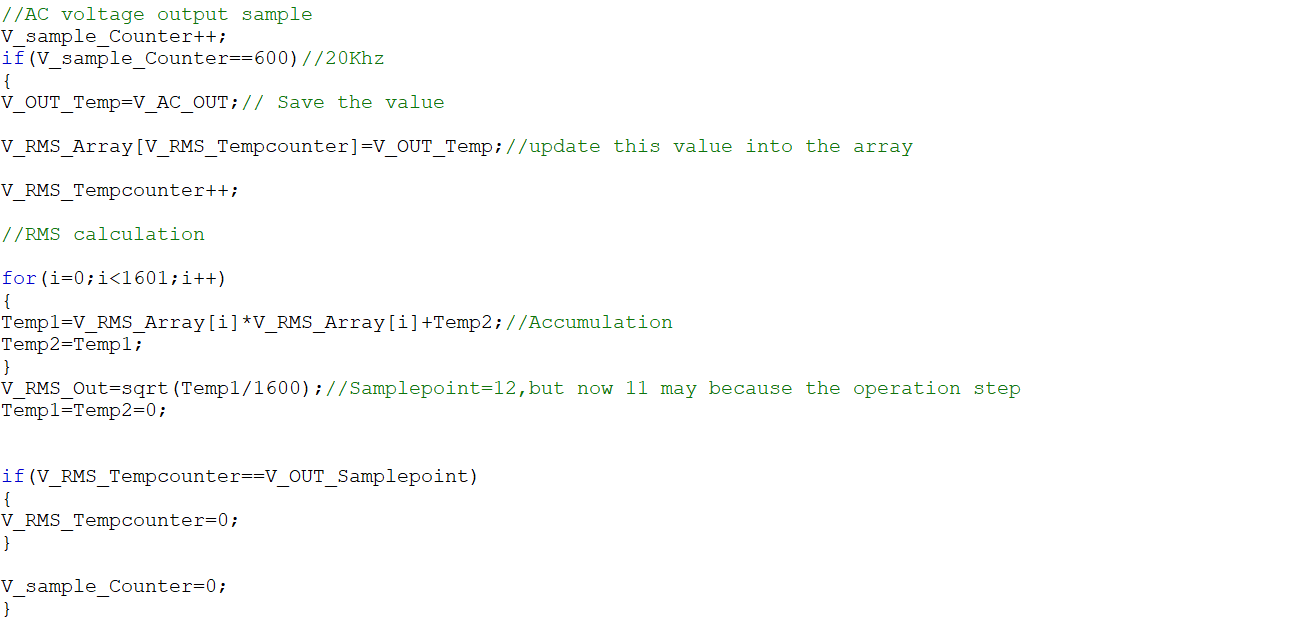
Sample rate is set to 20kHz, an addition counter operating at 120Mhz is utilized to trigger the sampling process. The sample is updated when the counter reaches 600. An array is used to save the sample voltage and calculate the RMS value of the output voltage, as Figure 3-7 shows. Code declaration and initialization were accomplished previously. The length of the array number is a trade-off between accuracy and update speed. A larger array number indicates better accuracy and lower speed. Figure 3-8 shows the simulation results for this module. To determine the exact length of the array, assume the window width is four periods of 50Hz sinusoidal wave and the sample rate is 20kHz, then an array length of 1600 is obtained.
 Figure 3-7 AC Voltage Sampling and RMS Value Calculation Code