SNOAAA7 April 2024 LMG3522R030
3.3.3 Sinusoidal and Sawtooth Wave Generator
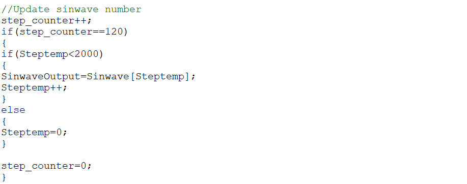
In PLECS, the update and output function are processed for each sample step. Therefore, the designer can consider the sample time as the system clock, using a counter to generate these signals with proper frequency. For the sinusoidal generator, first create an array and initialize this array with the number that changes sinusoidally. This array is set to 2000 to correspond with the current loop operating frequency.
 Figure 3-11 Sinusoidal Wave Generator
Logic is the same as in the sawtooth wave generator. One important aspect of totem-pole modulation is that two sawtooth signals need to be created; one for the positive cycle and the other for the negative cycle to generate a proper PWM signal, shown in Figure 2-3. The amplitude of these two carrier signals is from 0 to 1 and 0 to –1, respectively. It is worth mentioning that 2 signals are needed because of the case where one sawtooth signal with an amplitude from –1 to 1 to generate PWM signal is used. When the error signal is near zero, the lowest duty cycle is 50%, and the correct duty cycle is supposed to be near zero. Besides, the upper limit is set to 12 and divided by 120 to set the right frequency under the system clock. Figure 3-12 shows the sawtooth generator code.
 Figure 3-12 Sawtooth Wave Generator