SNOU180A June 2021 – September 2021 LM74701-Q1
3.2 Startup Reverse Polarity (–12 V)
- A –12-V source is connected to the VIN input of the LM74701-Q1EVM.
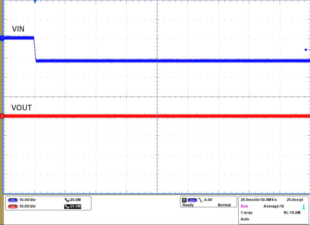
- Figure 3-2 shows that the output voltage remains at a constant 0 V in this situation.
- This test simulates the event of connecting a 12-V battery in the reverse direction; therefore, protecting the load from negative input voltages.
 Figure 3-2 Startup Reverse Polarity (–12
V)