SNOU200 October 2024 LMH6518
2.1 Preliminary Setup
The LMH6518 is easily configured with the USB2ANY interface adapter. The USB2ANY product page provides the required software and a detailed user’s guide for the adapter. The USB2ANY Explorer Software can be found under the Order & start development tab on the product’s homepage. The user’s guide, found under the Technical Documentation tab, highlights the general setup and operation of the adapter. The USB2ANY is shipped with a USB cable, a 10-pin cable, and a 30-pin cable. For communication with the LMH6518 evaluation board, the 10-pin cable is used as well as the USB cable to interface with the computer.
Once the software is installed follow the procedures below to configure the adapter to interface with the evaluation board.
- Open USB2ANY Explorer software and confirm the device is recognized when plugged into the computer using the USB cable. Users receive a message in the activity log confirming the controller was connected successfully.
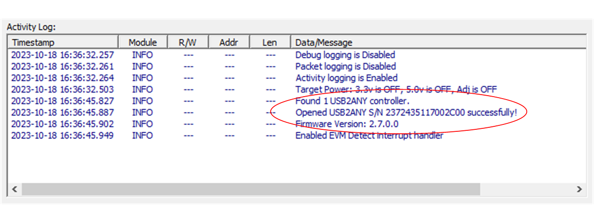 Figure 2-1 USB2ANY Detection Confirmation
 - Click the Select Interfaces and check the box next to SPI.
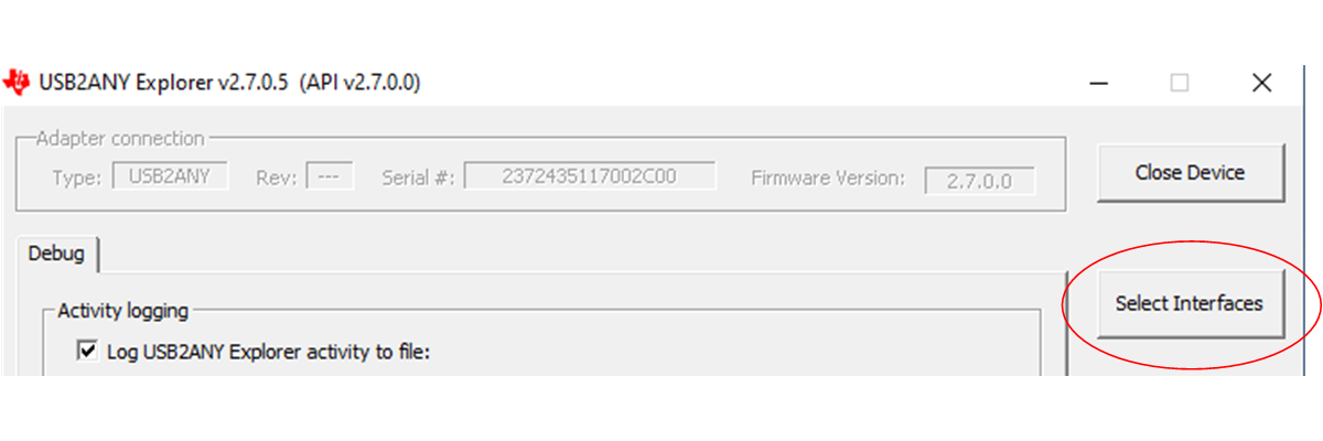 Figure 2-2 Adding SPI Tab to GUI
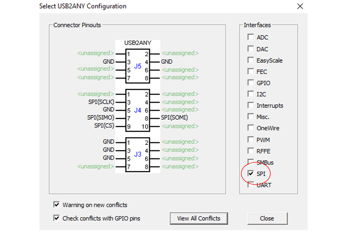 Figure 2-3 Selecting SPI Interface
 - Click on the SPI tab and select the settings as shown below that correspond to the LMH6518 SPI functionality.
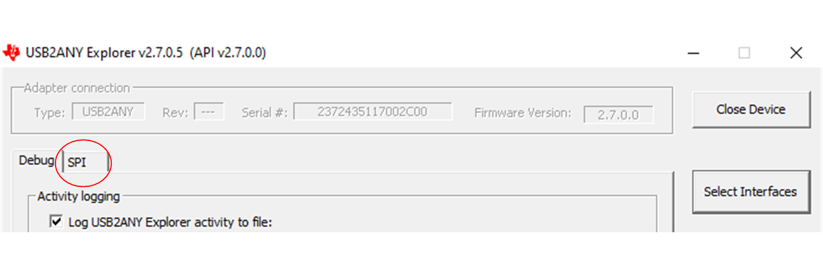 Figure 2-4 SPI Tab
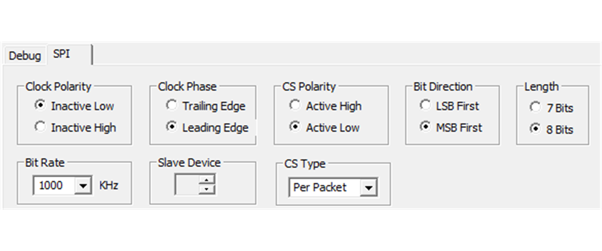 Figure 2-5 SPI Configuration
 - Set byte number to 3 bytes that corresponds to LMH6518 SPI communication length.
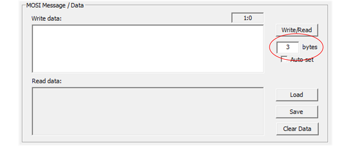 Figure 2-6 Setting Bytes for SPI Communication
 - Plug the 10-pin cable in the appropriate orientation into the USB2ANY adapter. The key on the 10-pin cable lines up with the USB2ANY.
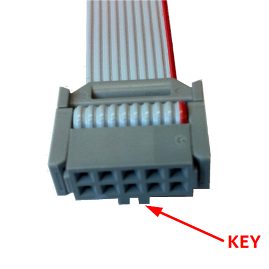 Figure 2-7 USB2ANY 10-Pin Header
 - Plug the other end of the ribbon cable into J2 of the LMH6518 evaluation board with the cable key on the side of the key label on the board.