SNOU200 October 2024 LMH6518
2.3 Jumper Information
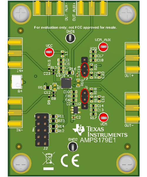
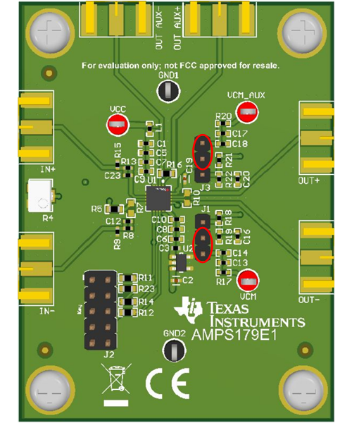
The LMH6518 evaluation board provides the option to bias the VOCM/VOCM_AUX pins using an onboard 1.2V bias or externally bias the pins by applying a voltage potential to the respective test points. To configure the intended bias source, adjust jumpers J1 and J3. Configuring the jumpers to the inner position bias the VOCM pins to the default 1.2V onboard bias. Placing the jumpers to the outer position bias the VOCM pins to the external voltage bias set by the VCM/VCM_AUX test points located on the board. The two positions are illustrated in Figure 2-9 and Figure 2-10.
 Figure 2-9 1.2V Onboard VCM Bias
Jumper Positions
 Figure 2-10 External VCM Bias Jumper
Positions