SNVA490B September 2011 – December 2021 LMR12010
5 Test Setup
Table 5-1 Demonstration Board Quick
Setup Procedures
| Step | Description | Notes |
|---|---|---|
| 1 | Connect a power supply to VIN terminals. | |
| 2 | Connect a load to VO terminals. | |
| 3 | EN should be connected to VIN for normal operation. Short this to ground to shut down the part. | |
| 4 | Set VIN = 5 V, with 0-A load applied. Check VO with a voltmeter. | Nominal 1.8 V |
| 5 | Apply a 1-A load and check VO. | Nominal 1.8 V |
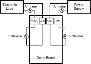
 Figure 5-1 Efficiency
Measurements
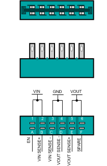
 Figure 5-3 Edge Connector
Schematic
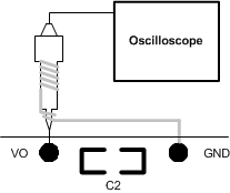
 Figure 5-2 Voltage Ripple
Measurements