SNVAA70 june 2023 LM5176 , LM5176-Q1
3.2 Current Ripple Measurement Through TEC Element
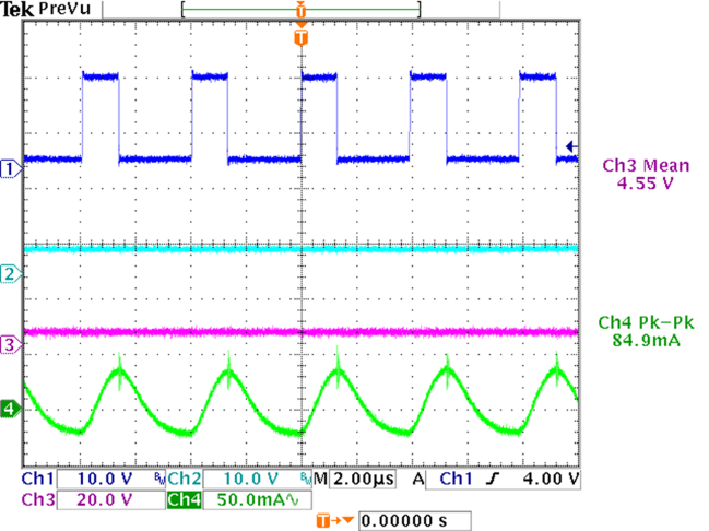
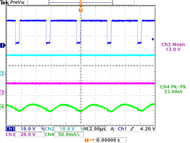
The maximum temperature differential across the element decreases if the ripple current increases. Thus, the maximum ripple current is recommended to be less than 10% for peak performance. Figure 3-7, Figure 3-8, Figure 3-9, and Figure 3-10 show the ripple current under different output voltages. All the tests meet the ripple requirement.
CH1: SW1, CH2: SW2, CH3: VOUT, CH4: IRipple
CH1: SW1, CH2: SW2, CH3: VOUT, CH4: IRipple Figure 3-7 15-V Input, 5-V Output. CH1: SW1, CH2: SW2, CH3: VOUT, CH4: IRipple
 Figure 3-7 15-V Input, 5-V Output. CH1: SW1, CH2: SW2, CH3: VOUT, CH4: IRipple
CH1: SW1, CH2: SW2, CH3: VOUT, CH4: IRipple Figure 3-9 15-V Input, 17-V Output. CH1: SW1, CH2: SW2, CH3: VOUT, CH4: IRipple
 Figure 3-9 15-V Input, 17-V Output. CH1: SW1, CH2: SW2, CH3: VOUT, CH4: IRipple
CH1: SW1, CH2: SW2, CH3: VOUT, CH4: IRipple Figure 3-8 15-V Input, 13-V Output. CH1: SW1, CH2: SW2, CH3: VOUT, CH4: IRipple
 Figure 3-8 15-V Input, 13-V Output. CH1: SW1, CH2: SW2, CH3: VOUT, CH4: IRipple
CH1: SW1, CH2: SW2, CH3: VOUT, CH4: IRipple Figure 3-10 15-V Input, 25-V Output. CH1: SW1, CH2: SW2, CH3: VOUT, CH4: IRipple
 Figure 3-10 15-V Input, 25-V Output. CH1: SW1, CH2: SW2, CH3: VOUT, CH4: IRipple