SNVAA80 July 2024 LM5177
2 Reverse Current Operation
The LM5177 device incorporates a precise inner voltage loop error amplifier, accurately reflecting the voltage at the COMP Pin onto the nominal peak current value of the inductor. This design provides effective voltage regulation.
Figure 2-1 illustrates the inner voltage loop of the buck-boost controller, featuring peak and average current sensing. The LM5177 data sheet provides detailed specifications and performance data for optimizing designs for efficiency and performance across applications.
 Figure 2-1 Control Loops for Buck-boost Controller
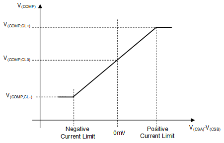
Figure 2-2 shows the inner voltage loop error for the voltage/current (V/I) characteristics of the amplifier. This graph illustrates how the voltage at the COMP pin VCOMP influences the direction of the converter current flow. Two threshold values are crucial, the Vcomp, CL+ at 1.25V and Vcomp, CL- at 0.24V. If VCOMP exceeds the Vcomp, CL0 threshold, which is typically 1.25V, the current flows forward through the converter. Conversely, if VCOMP falls below this threshold, the converter current flows in the reverse direction.
 Figure 2-2 Control Function for the Peak Current Sense Voltage Versus VCOMP
Moreover, the peak current sense resistor sets the positive and negative limits for peak current. This resistor determines the maximum current that can flow in either direction through the converter. In addition, the average current limiter loop plays a pivotal role in controlling current flow. By adjusting the VCOMP value, this limiter loop can cap the forward or reverse current, verifying that the current remains within predefined limits. Understanding these V/I characteristics is crucial for designing and optimizing the performance of the buck-boost converter. By analyzing these parameters, the behavior of the converter can be adjusted to meet specific requirements and provide reliable operation across various conditions.