SNVAA87 august   2023 LMR38020


  1.   1
  2.   Abstract
  3.   Trademarks
  4. 1Introduction
    1. 1.1 Micro Inverter System
    2. 1.2 Typical Power Tree and Design Requirements
  5. 2Conventional Flyback Design Challenges
    1. 2.1 SSR Design Challenges
    2. 2.2 PSR Design Challenges
  6. 3New Fly-Buck Design
    1. 3.1 LMR38020 Overview
    2. 3.2 Comparison with Conventional Flyback
    3. 3.3 Design Considerations
    4. 3.4 LMR38020 Fly-Buck Design Example
  7. 4Bench Test and Result
    1. 4.1 Start Up
    2. 4.2 Typical Switching Waveforms Under Steady State
    3. 4.3 Efficiency
    4. 4.4 Load Regulation
    5. 4.5 Short Circuit
    6. 4.6 Thermal Performance
  8. 5Summary
  9. 6References

Start Up

The typical start-up behavior shows the secondary output voltage tracking the primary output voltage during the soft start sequence.

In the OCP blanking time (18 ms as stated in the data sheet), since the device operates in PFM mode during this period, there is a drop of the secondary output voltage. The heavier secondary load or lighter primary load brings more drop. The process is to add a small amount of preload on the primary side as hinted in Section 3.3
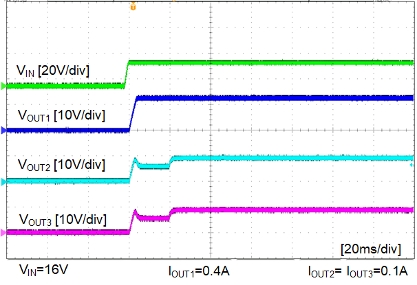
GUID-20230807-SS0I-X3GF-ZKHK-K49RCVMPQJSD-low.pngFigure 4-3 Start Up, Full Load, VIN=16 V
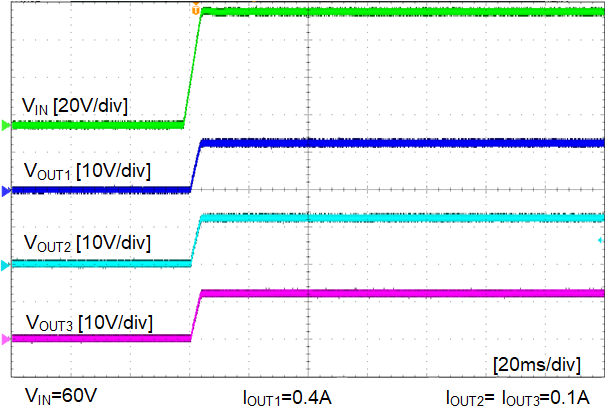
GUID-20230807-SS0I-DRTW-ZDF8-M0WQTPSZ4TNZ-low.pngFigure 4-4 Start Up, Full Load, VIN=60 V