SNVAA87 august 2023 LMR38020
4 Bench Test and Result
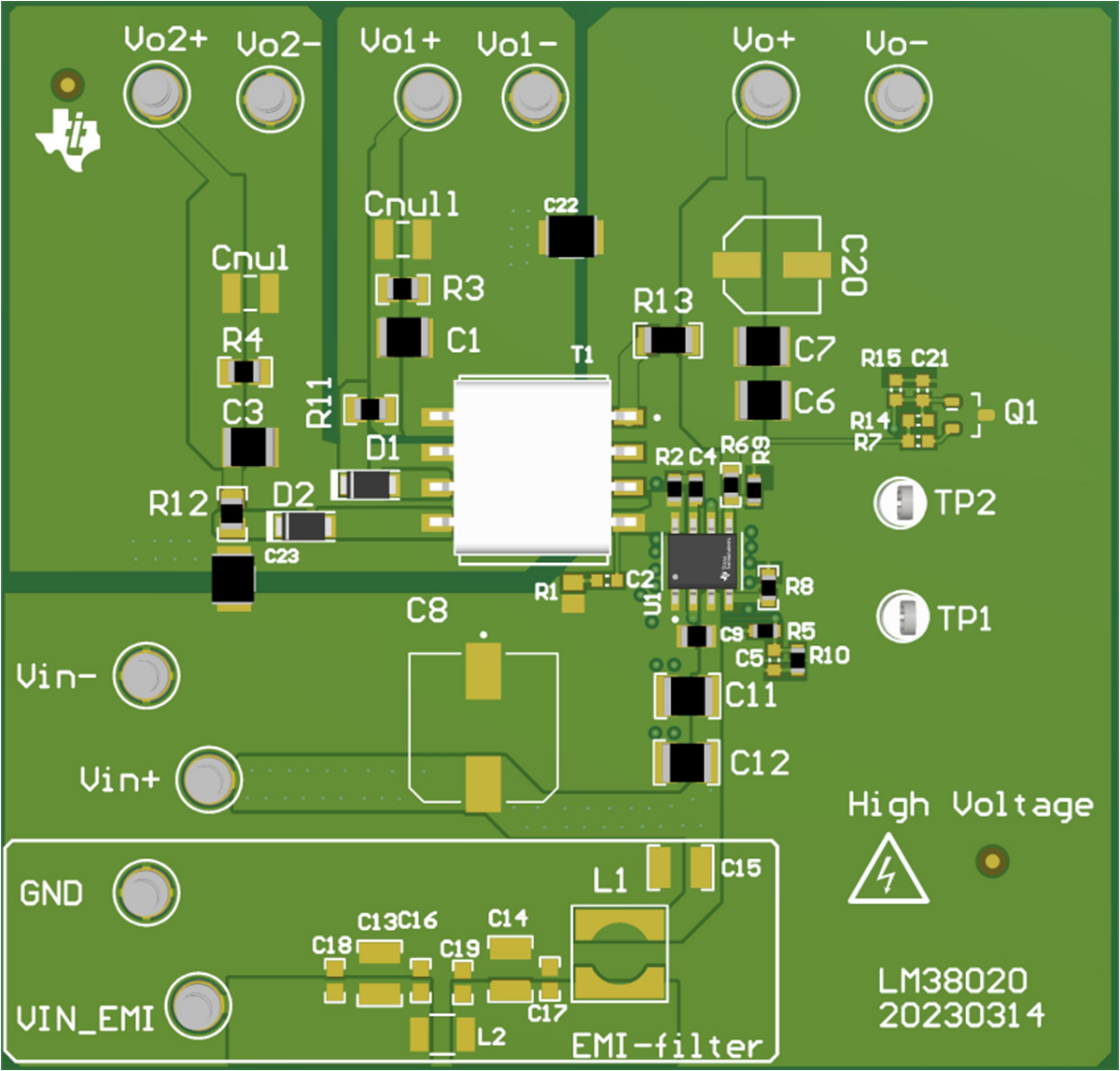
Figure 4-1 shows the LMR38020 Fly-Buck™ application schematic for micro inverter and Figure 4-2 shows the demo board top view.
 Figure 4-1 LMR38020 Fly-Buck Application Schematic for Micro Inverter
 Figure 4-2 LMR38020 Fly-Buck Demo board for Micro
Inverter
Figure 4-2 LMR38020 Fly-Buck Demo board for Micro
InverterThe demo board is tested almost over full-range line and load variation. In short, the efficiency can be up to 96% at VIN=24V and full load, as shown in Figure 4-9 and Figure 4-10. The regulation tolerance on the primary Vout is approximately 1% and the secondary Vout is <10% as shown in Figure 4-11 and Figure 4-12.