SNVU191B October 2012 – December 2021 LMR12020
4.6 Typical Test Setup
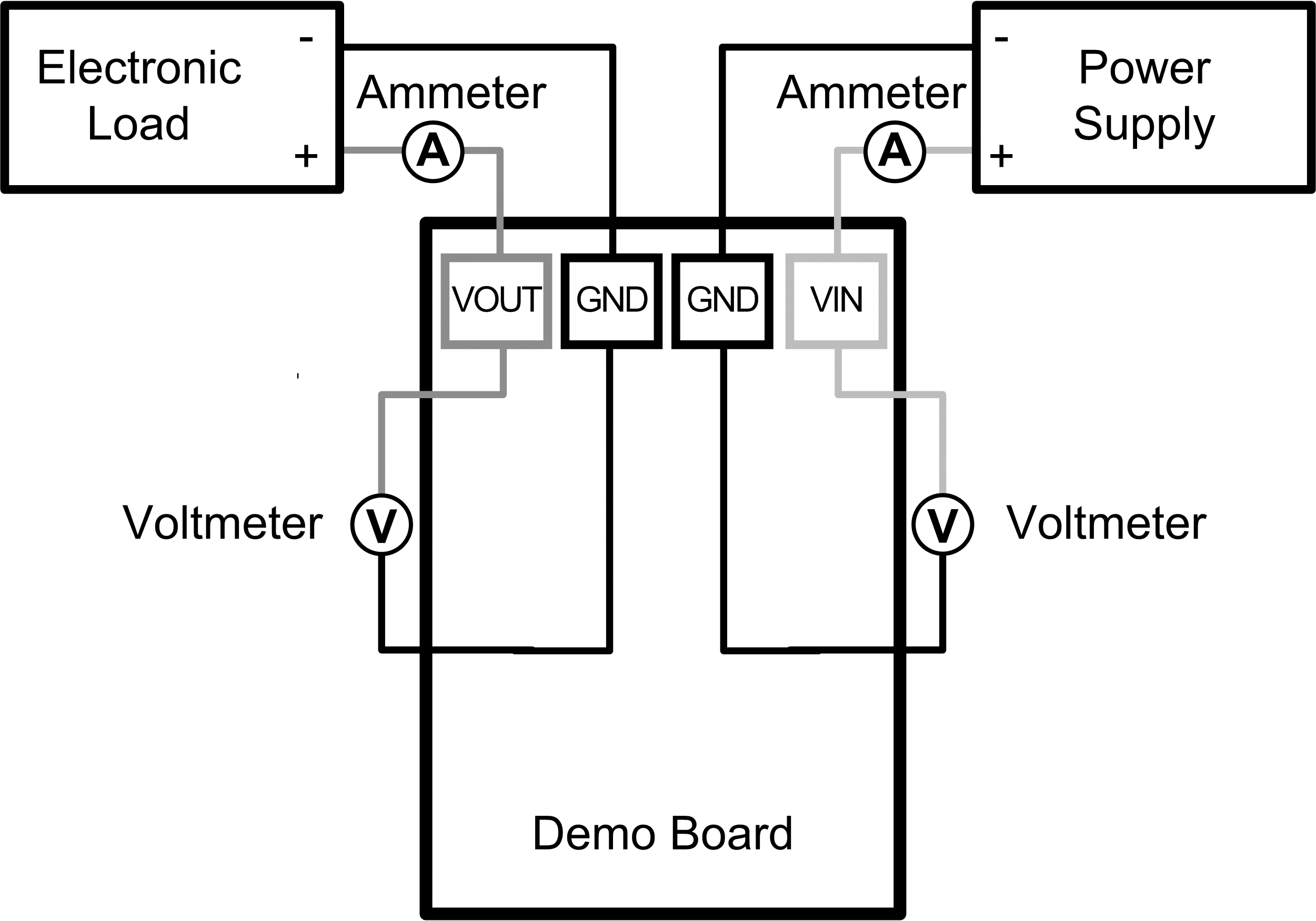
 Figure 4-1 Efficiency Measurements
 Figure 4-2 Voltage Ripple Measurements
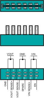
 Figure 4-3 Edge Connector Schematic
SNVU191B October 2012 – December 2021 LMR12020
 Figure 4-1 Efficiency Measurements
 Figure 4-2 Voltage Ripple Measurements
 Figure 4-3 Edge Connector Schematic