SNVU697 September 2020 LMQ62440-Q1
2 Quick Start
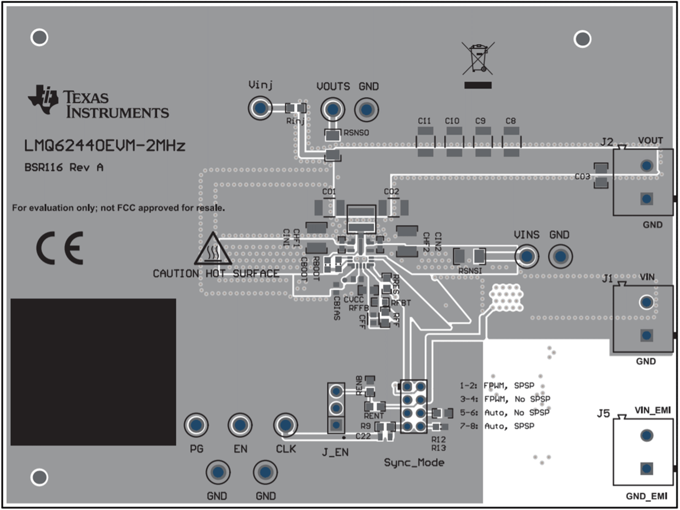
- Connect the input voltage supply between the VIN and GND connectors or between VIN_EMI and GND_EMI to include the on-board input filter in the input path. Use short and thick gauge wires to minimize inductance and I-R drop. Note that current-limited sense points for VIN (VINS) and VOUT (VOUTS) are provided. Do not connect input voltage supply to VINS, as series current-limiting resistor has low power rating.
- Connect the load of the converter between VOUT and GND connectors using short and thick wires. Do not connect load to VOUTS, as series current-limiting resistor has low power rating.
- Set the supply voltage between 3 V to 36 V. Account for dropout of converter by setting supply to approximately 6 V to have 5 V output, as an example.
- Set the current limit of the supply to an appropriate level to supply needed current and protection.
- Turn on the power supply. With the default configuration, the EVM powers up and provides VOUT = 5 V.
- Monitor the output voltage. The maximum (DC) load current is 4 A with the LMQ62440-Q1.
See Figure 2-1 for the location of the connectors.
 Figure 2-1 Top
Component View of LMQ62440EVM-PP-2MHz