SNVU797C April 2022 – October 2024 LM5177
4.4 Step Load Response
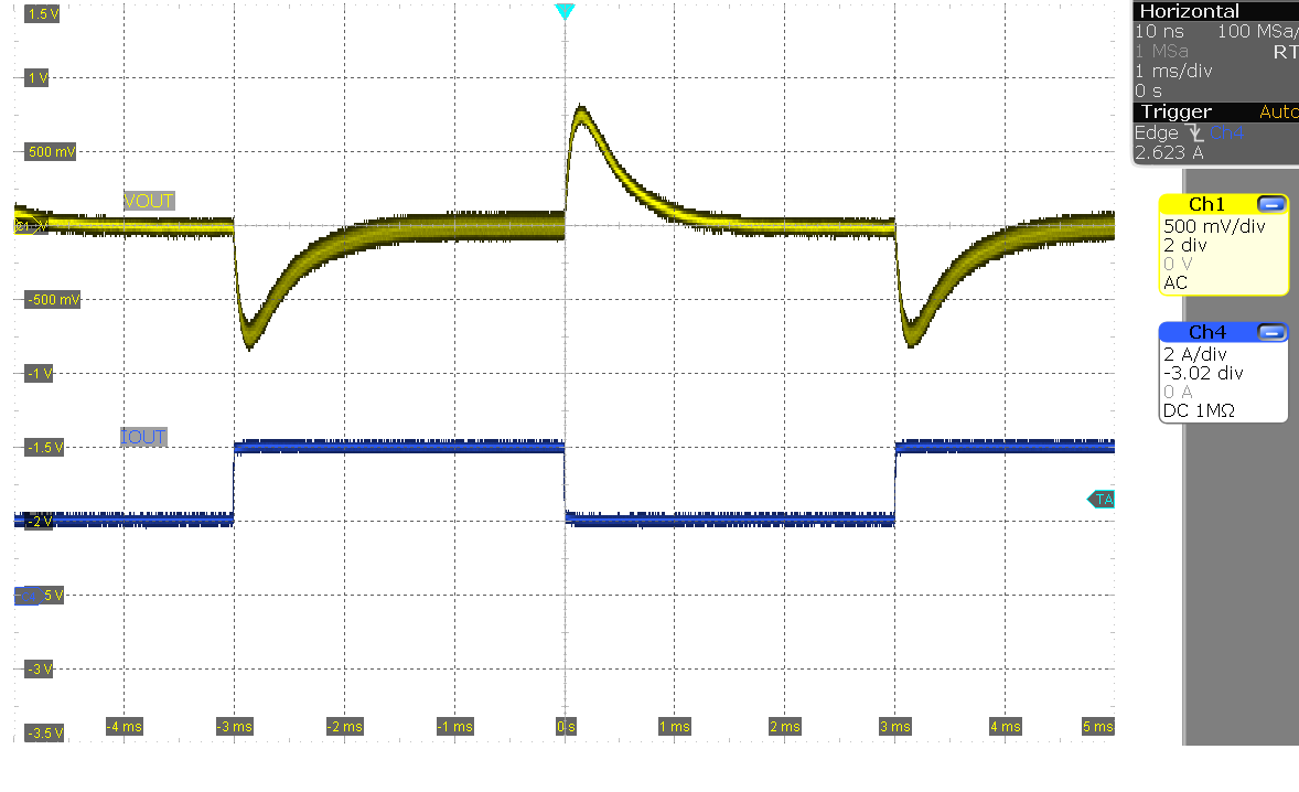 Figure 4-17 Load Step
(VIN = 7 V, IOUT = 2 A–4 A)
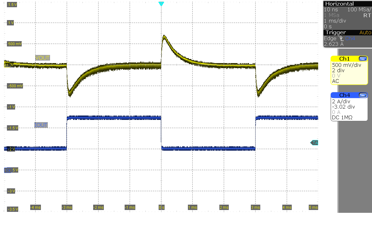 Figure 4-19 Load Step
(VIN = 12 V, IOUT = 2 A–5 A)
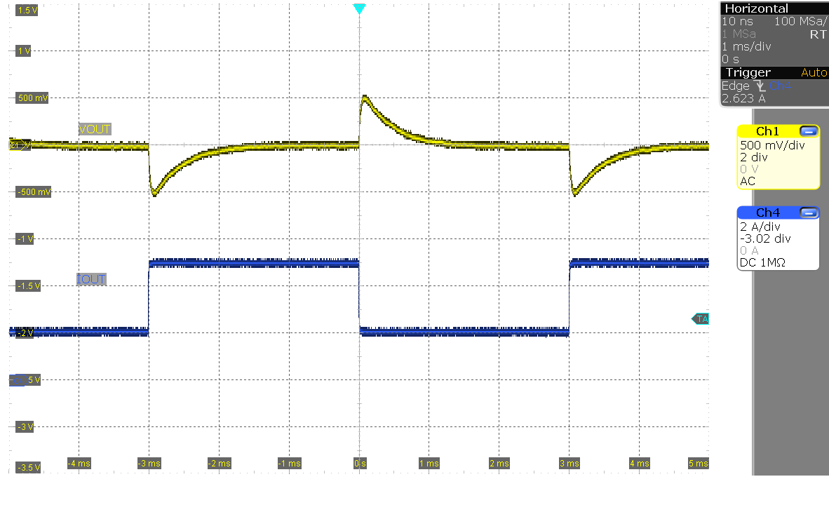 Figure 4-21 Load Step
(VIN = 24 V, IOUT = 2 A–5 A)
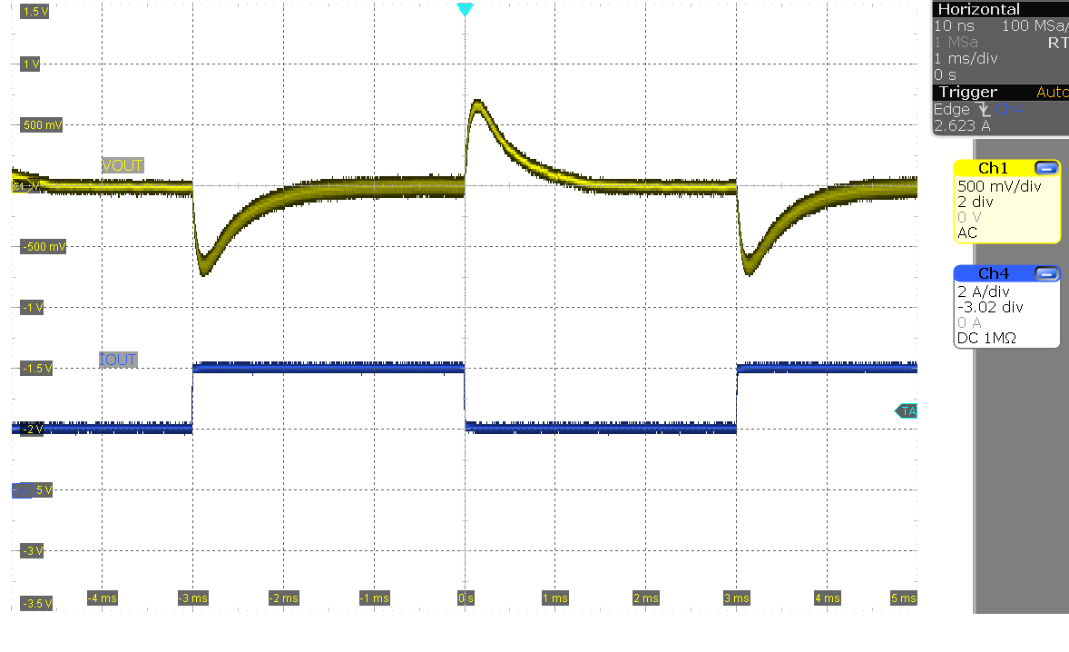 Figure 4-18 Load Step
(VIN = 8 V, IOUT = 2 A–4 A)
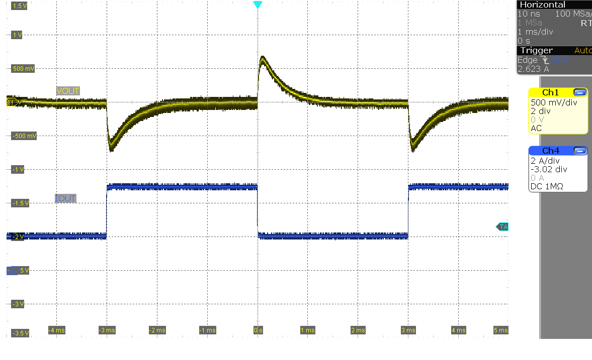 Figure 4-20 Load Step
(VIN = 18 V, IOUT = 2 A–5 A)
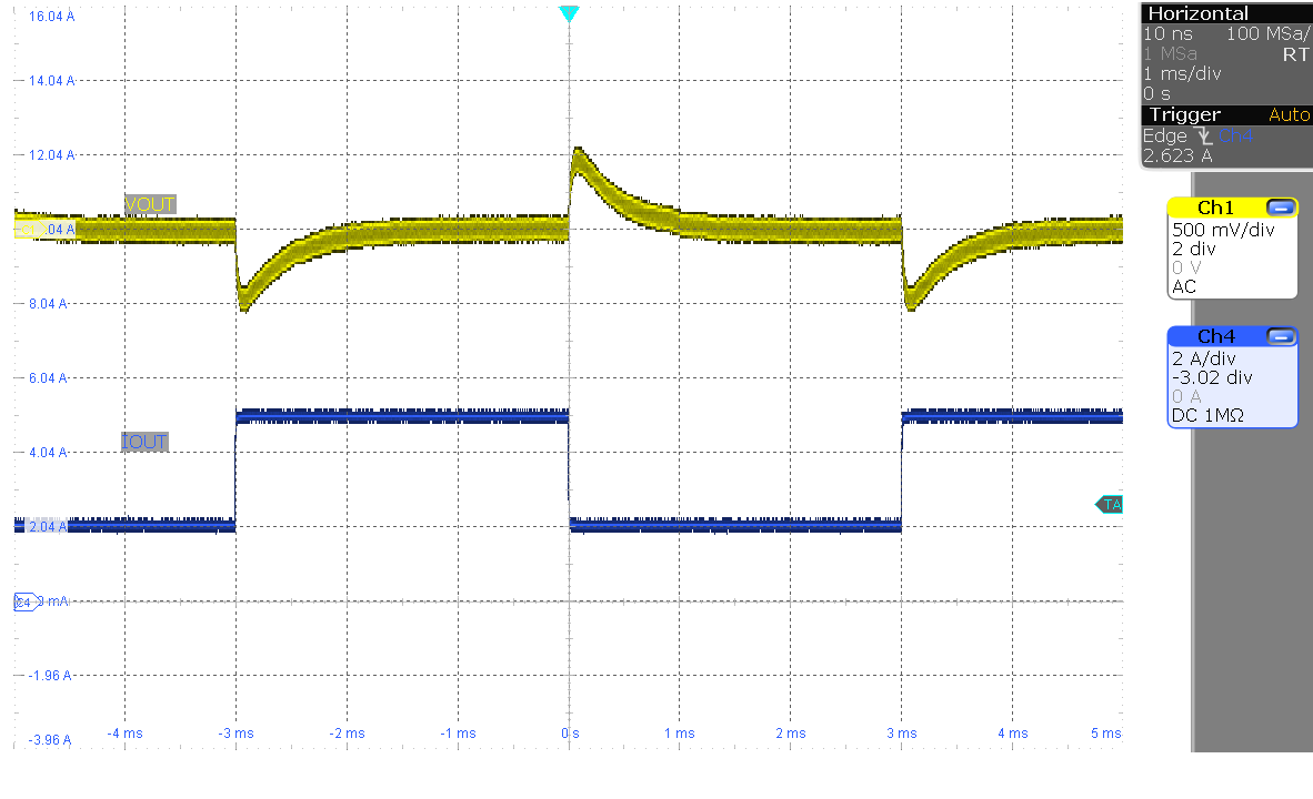 Figure 4-22 Load Step
(VIN = 36 V, IOUT = 2 A–5 A)