SNVU915 August 2024 LMG2100R026
2.2.3 Step 3: Measure SW Voltage
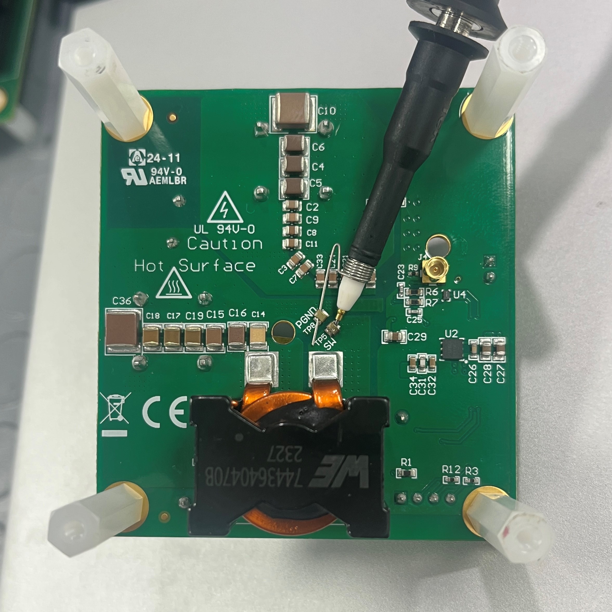
To observe the SW node, connect a tip and barrel probe to SW node (TP5) and PGND (TP8), as shown in Figure 2-2. This verifies that the measurement loop is small and, hence, accurately reflects the behavior of the SW node. If a large loop is used, due to the high dv/dt on the SW node and the parasitic impedance (inductance) of the loop, then a large amount of ringing is observed on the SW node measurements. This ringing is not representative of the device performance, but is rather a measurement artifact. The probe connection must be made prior to the board being powered up and one must verify that appropriate safety precautions are taken. Pads for TP5 and TP8 are provided on the top side to make the measurement convenient, if the heat sink is not being used.
Connect the scope probe to measure the SW node as shown in Figure 2-2. Notice the small pigtail used to minimize the ground loop.
 Figure 2-2 Measuring the SW Node