SNWA014 November 2023 LMH2110
2.1 Block Diagram
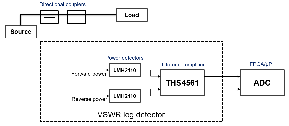
The VSWR detector employs two power detectors directionally coupled to a transmission line, one coupled in a forward direction to capture forward power and another coupled in the reverse direction to capture reflected power. The outputs of the two power detectors, LMH2110 are fed into a fully-differential amplifier, THS4561 used in a difference mode to get the ratio of forward power to reflected power as a differential voltage. The THS4561 is selected because of the high bandwidth, which allows a quicker cycle time for VSWR calculation. The outputs of the THS4561 are then fed to an ADC on a FPGA or an MCU/MPU where the value of VSWR can be calculated.
The coupler that needs to be used is a directional coupler, to maintain precise power reading based on the directive and coupling factor of the coupler. A bi-directional coupler can also be used if the specifications work for the accuracy requirements.
 Figure 2-1 VSWR Measurement System Block Diagram
The output voltage swing of the THS4561 is an important parameter as a higher, unregulated output swing can saturate the ADC and give incorrect measurement values. THS4561, operating as a difference amplifier, has the input voltage set according to the output swing required using resistor dividers on the inputs and the gain setting of the THS4561.