SPRACM9B June 2019 – November 2020 F29H850TU , F29H859TU-Q1 , TMS320F28384D , TMS320F28384S , TMS320F28386D , TMS320F28386S , TMS320F28388D , TMS320F28388S , TMS320F28P650DH , TMS320F28P650DK , TMS320F28P650SH , TMS320F28P650SK , TMS320F28P659DH-Q1 , TMS320F28P659DK-Q1 , TMS320F28P659SH-Q1
- Trademarks
- 1 Introduction
- 2 Benefits of the TMS320F2838x MCU for High-Bandwidth Current Loop
- 3 Current Loops in Servo Drives
- 4 Outline of the Fast Current Loop Library
- 5 Fast Current Loop Evaluation
- 6 Incremental Build Level 1
- 7 Incremental Build Level 2
- 8 Incremental Build Level 3
- 9 Incremental Build Level 4
- 10Incremental Build Level 5
- 11Incremental Build Level 6
- 12Incremental Build Level 7
- 13Incremental Build Level 8
- 14References
- 15Revision History
6 Incremental Build Level 1
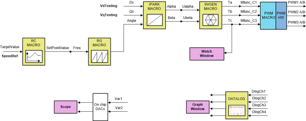
The block diagram of the system built in BUILD LEVEL 1 is shown in Figure 6-1. During this step, keep the motor disconnected.
 Figure 6-1 Level 1 Block Diagram
Assuming the load and build steps described in the DesignDRIVE IDDK User Guide completed successfully, this section describes the steps for a “minimum” system check-out which confirms operation of system interrupt, the peripheral and target independent inverse park transformation and space vector generator modules, and the PWM initializations and update modules.
- Open fcl_f2838x_tmdxiddk_settings_cpu1.h and select the level 1 incremental build option by setting the BUILDLEVEL to FCL_LEVEL1 (#define BUILDLEVEL FCL_LEVEL1).
- Right-click on the project name and click Rebuild Project.
- When the build is complete, click on debug button, reset the CPU, restart, enable real time mode, and run.
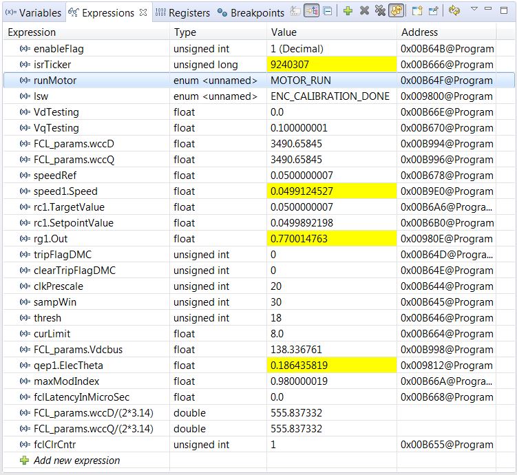
- Add variables to the expressions window by right-clicking within the Expressions Window and importing the fcl_f2838x_tmdxiddk_vars_cpu1.txt file from the debug directory. Figure 6-2 shows the variables imported into the Expressions Window from this file. Ignore the values shown against the variables for now.
 Figure 6-2 Expressions Window for Build Level 2
 - Set enableFlag to 1 in the watch window. The variable named isrTicker is incrementally increased, as seen in the watch windows, to confirm the interrupt working properly.
In the software, the key variables to be adjusted are:- speedRef : for changing the rotor speed in per-unit.
- VdTesting : for changing the d-qxis voltage in per-unit.
- VqTesting : for changing the q-axis voltage in per-unit.