SPRACO3 October 2019 INA240 , LMG5200 , TMS320F280021 , TMS320F280021-Q1 , TMS320F280023 , TMS320F280023-Q1 , TMS320F280023C , TMS320F280025 , TMS320F280025-Q1 , TMS320F280025C , TMS320F280025C-Q1 , TMS320F280040-Q1 , TMS320F280040C-Q1 , TMS320F280041 , TMS320F280041-Q1 , TMS320F280041C , TMS320F280041C-Q1 , TMS320F280045 , TMS320F280048-Q1 , TMS320F280048C-Q1 , TMS320F280049 , TMS320F280049-Q1 , TMS320F280049C , TMS320F280049C-Q1 , TMS320F28374D , TMS320F28374S , TMS320F28375D , TMS320F28375S , TMS320F28375S-Q1 , TMS320F28376D , TMS320F28376S , TMS320F28377D , TMS320F28377D-EP , TMS320F28377D-Q1 , TMS320F28377S , TMS320F28377S-Q1 , TMS320F28378D , TMS320F28378S , TMS320F28379D , TMS320F28379D-Q1 , TMS320F28379S
-
Dual-Axis Motor Control Using FCL and SFRA On a Single C2000 MCU
- Trademarks
- 1 Introduction
- 2 Benefits of the C2000 for High-Bandwidth Current Loop
- 3 Current Loops in Servo Drives
- 4 PWM Update Latency for Dual Motor
- 5 Outline of the Fast Current Loop Library
- 6 Evaluation Platform Setup
- 7 System Software Integration and Testing
- 8 Summary
- 9 References
7.1 Incremental Build Level 1
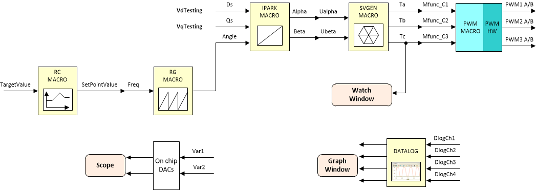
The block diagram of the system built in BUILD LEVEL 1 is shown in Figure 18. During this step, keep the motor disconnected.
 Figure 18. Level 1 Block Diagram
 Assuming the load and build steps described in the Section 6.2.2 completed successfully. This section describes the steps for a minimum system check-out, which confirms operation of system interrupt, the peripheral and target independent inverse park transformation, space vector generator modules, and the peripheral dependent PWM initialization and update modules.
- Open "dual_axis_servo_drive_settings.h" from the project directory. Select the level 1 incremental build option by setting the BUILDLEVEL to FCL_LEVEL1 (#define BUILDLEVEL FCL_LEVEL1).
- Right click on the project name and click Rebuild Project.
- When the build is complete, click on debug button, reset CPU, restart, enable real time mode, and run.
- Add variables to the expressions window by right clicking within the Expressions Window and importing the file "dual_axis_servo_drive_vars.txt" from the debug directory and the expressions window will look as shown in Figure 14 in Section 6.2.2.
- Set 'enableFlag' to 1 in the expressions window. The variables named 'motorVars[0].isrTicker' and 'motorVars[1].isrTicker' are incrementally increased as shown in Expressions window to confirm the interrupts are working properly. In the software, the key variables within the structure of 'motorVars[0]' and 'motorVars[1]' to be adjusted are summarized below:
- motorVars[0].speedRef: for changing the rotor speed in per-unit.
- VdTesting: for changing the d-qxis voltage in per-unit.
- VqTesting: for changing the q-axis voltage in per-unit.
NOTE
The tests suggested below for motor 1 by setting 'motorVars[0]' that can be repeated for motor 2 by setting 'motorVars[1]' also to verify the hardware and software integrity in subsequent build levels.