SPRACP3C November 2019 – December 2021 AWR6843 , AWR6843AOP , IWR1443 , IWR1642 , IWR6443 , IWR6843 , IWR6843AOP
- Trademarks
- 1Introduction
- 2Typical Certification Procedure
- 3Regulatory Compliance Overview
- 4Tools and Setup
- 5Common Issues and Resolutions
- 6References
- 7Revision History
5.5.2 Frequency Stability Over Temperature and Voltage Range
Problem Statement: Frequency is not within the limit over the temperature and voltage range.
Solution: Adjust the capacitors on the clock to ensure ~0 PPM deviation at room temperature.
Deep Dive:
FCC part 15.255, Frequency stability: Fundamental emissions must be contained within the frequency bands specified in this section during all conditions of operation. Equipment is presumed to operate over the temperature range −20 to + 50 degrees Celsius with an input voltage variation of 85% to 115% of rated input voltage, unless justification is presented to demonstrate otherwise.
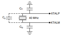
 Figure 5-6 40-Mhz Crystal Capacitance
- Cp is the parasitic capacitance
- Cf1 and Cf2 are capacitors in parallel
IWR6843 requires a 40-MHz crystal or external oscillator to the CLKP pin; this is used for initial boot up and as reference for the internal APLL and other clocks. For the IWR6843ISK EVM, the crystal is implemented as shown in Figure 5-6. The capacitors are chosen to satisfy requirement shown in Table 5-2.
| Name | Description | Min | Typ | Max | Unit |
|---|---|---|---|---|---|
| Fp | Parallel resonance crystal frequency | 40 | MHz | ||
| CL | Crystal load capacitance | 5 | 8 | 12 | pF |
| Temperature range | Expected temp range of operation | -40 | 105 | °C | |
| Frequency tolerance | Crystal frequency tolerance | -50 | 50 | ppm |
To meet the FCC requirements, the capacitors should be tuned such that the oscillator frequency deviation is at 0 ppm at room temperature and frequency deviation stays within the frequency band across voltage and temperature .