SPRUI30H November 2015 – May 2024 DRA745 , DRA746 , DRA750 , DRA756
- 1
- Read This First
-
1 Introduction
- 1.1 DRA75x, DRA74x Overview
- 1.2 DRA75x, DRA74x Environment
- 1.3
DRA75x, DRA74x Description
- 1.3.1 MPU Subsystem
- 1.3.2 DSP Subsystems
- 1.3.3 EVE Subsystems
- 1.3.4 IPU Subsystems
- 1.3.5 IVA-HD Subsystem
- 1.3.6 Display Subsystem
- 1.3.7 Video Processing Subsystem
- 1.3.8 Video Capture
- 1.3.9 3D GPU Subsystem
- 1.3.10 BB2D Subsystem
- 1.3.11 On-Chip Debug Support
- 1.3.12 Power, Reset, and Clock Management
- 1.3.13 On-Chip Memory
- 1.3.14 Memory Management
- 1.3.15 External Memory Interfaces
- 1.3.16 System and Connectivity Peripherals
- 1.4 DRA75x, DRA74x Family
- 1.5 DRA75x, DRA74x Device Identification
- 1.6 DRA75x, DRA74x Package Characteristics Overview
- 2 Memory Mapping
-
3 Power, Reset, and Clock Management
- 3.1
Device Power Management Introduction
- 3.1.1
Device Power-Management Architecture Building Blocks
- 3.1.1.1 Clock Management
- 3.1.1.2 Power Management
- 3.1.1.3 Voltage Management
- 3.1.2 Power-Management Techniques
- 3.1.1
Device Power-Management Architecture Building Blocks
- 3.2 PRCM Subsystem Overview
- 3.3 PRCM Subsystem Environment
- 3.4 PRCM Subsystem Integration
- 3.5
Reset Management Functional Description
- 3.5.1 Overview
- 3.5.2 General Characteristics of Reset Signals
- 3.5.3 Reset Sources
- 3.5.4 Reset Logging
- 3.5.5 Reset Domains
- 3.5.6
Reset Sequences
- 3.5.6.1 MPU Subsystem Power-On Reset Sequence
- 3.5.6.2 MPU Subsystem Warm Reset Sequence
- 3.5.6.3 MPU Subsystem Reset Sequence on Sleep and Wake-Up Transitions From RETENTION State
- 3.5.6.4 IVA Subsystem Power-On Reset Sequence
- 3.5.6.5 IVA Subsystem Software Warm Reset Sequence
- 3.5.6.6 DSP1 Subsystem Power-On Reset Sequence
- 3.5.6.7 DSP1 Subsystem Software Warm Reset Sequence
- 3.5.6.8 DSP2 Subsystem Power-On Reset Sequence
- 3.5.6.9 DSP2 Subsystem Software Warm Reset Sequence
- 3.5.6.10 IPU1 Subsystem Power-On Reset Sequence
- 3.5.6.11 IPU1 Subsystem Software Warm Reset Sequence
- 3.5.6.12 IPU2 Subsystem Power-On Reset Sequence
- 3.5.6.13 IPU2 Subsystem Software Warm Reset Sequence
- 3.5.6.14 EVE1 Subsystem Power-On Reset Sequence
- 3.5.6.15 EVE1 Subsystem Software Warm Reset Sequence
- 3.5.6.16 EVE2 Subsystem Power-On Reset Sequence
- 3.5.6.17 EVE2 Subsystem Software Warm Reset Sequence
- 3.5.6.18 Global Warm Reset Sequence
- 3.6
Clock Management Functional Description
- 3.6.1 Overview
- 3.6.2 External Clock Inputs
- 3.6.3
Internal Clock Sources and Generators
- 3.6.3.1 PRM Clock Source
- 3.6.3.2 CM Clock Source
- 3.6.3.3 Generic DPLL Overview
- 3.6.3.4 DPLL_PER Description
- 3.6.3.5 DPLL_CORE Description
- 3.6.3.6 DPLL_ABE Description
- 3.6.3.7 DPLL_MPU Description
- 3.6.3.8 DPLL_IVA Description
- 3.6.3.9 DPLL_USB Description
- 3.6.3.10 DPLL_EVE Description
- 3.6.3.11 DPLL_DSP Description
- 3.6.3.12 DPLL_GMAC Description
- 3.6.3.13 DPLL_GPU Description
- 3.6.3.14 DPLL_DDR Description
- 3.6.3.15 DPLL_PCIE_REF Description
- 3.6.3.16 APLL_PCIE Description
- 3.6.4
Clock Domains
- 3.6.4.1 CD_WKUPAON Clock Domain
- 3.6.4.2 CD_DSP1 Clock Domain
- 3.6.4.3 CD_DSP2 Clock Domain
- 3.6.4.4 CD_CUSTEFUSE Clock Domain
- 3.6.4.5 CD_MPU Clock Domain
- 3.6.4.6 CD_L4PER1 Clock Domain
- 3.6.4.7 CD_L4PER2 Clock Domain
- 3.6.4.8 CD_L4PER3 Clock Domain
- 3.6.4.9 CD_L4SEC Clock Domain
- 3.6.4.10 CD_L3INIT Clock Domain
- 3.6.4.11 CD_IVA Clock Domain
- 3.6.4.12 CD_GPU Description
- 3.6.4.13 CD_EMU Clock Domain
- 3.6.4.14 CD_DSS Clock Domain
- 3.6.4.15 CD_L4_CFG Clock Domain
- 3.6.4.16 CD_L3_INSTR Clock Domain
- 3.6.4.17 CD_L3_MAIN1 Clock Domain
- 3.6.4.18 CD_EMIF Clock Domain
- 3.6.4.19 CD_IPU Clock Domain
- 3.6.4.20 CD_IPU1 Clock Domain
- 3.6.4.21 CD_IPU2 Clock Domain
- 3.6.4.22 CD_DMA Clock Domain
- 3.6.4.23 CD_ATL Clock Domain
- 3.6.4.24 CD_CAM Clock Domain
- 3.6.4.25 CD_GMAC Clock Domain
- 3.6.4.26 CD_VPE Clock Domain
- 3.6.4.27 CD_EVE1 Clock Domain
- 3.6.4.28 CD_EVE2 Clock Domain
- 3.6.4.29 CD_RTC Clock Domain
- 3.6.4.30 CD_PCIE Clock Domain
- 3.7
Power Management Functional Description
- 3.7.1 PD_WKUPAON Description
- 3.7.2 PD_DSP1 Description
- 3.7.3 PD_DSP2 Description
- 3.7.4 PD_CUSTEFUSE Description
- 3.7.5 PD_MPU Description
- 3.7.6 PD_IPU Description
- 3.7.7 PD_L3INIT Description
- 3.7.8 PD_L4PER Description
- 3.7.9 PD_IVA Description
- 3.7.10 PD_GPU Description
- 3.7.11 PD_EMU Description
- 3.7.12 PD_DSS Description
- 3.7.13 PD_CORE Description
- 3.7.14 PD_CAM Description
- 3.7.15 PD_MPUAON Description
- 3.7.16 PD_MMAON Description
- 3.7.17 PD_COREAON Description
- 3.7.18 PD_VPE Description
- 3.7.19 PD_EVE1 Description
- 3.7.20 PD_EVE2 Description
- 3.7.21 PD_RTC Description
- 3.8 Voltage-Management Functional Description
- 3.9 Device Low-Power States
- 3.10
PRCM Module Programming Guide
- 3.10.1 DPLLs Low-Level Programming Models
- 3.10.2 Clock Management Low-Level Programming Models
- 3.10.3 Power Management Low-Level Programming Models
- 3.11 546
- 3.12 PRCM Software Configuration for OPP_PLUS
- 3.13
PRCM Register Manual
- 3.13.1 PRCM Instance Summary
- 3.13.2 CM_CORE_AON__CKGEN Registers
- 3.13.3 CM_CORE_AON__DSP1 Registers
- 3.13.4 CM_CORE_AON__DSP2 Registers
- 3.13.5 CM_CORE_AON__EVE1 Registers
- 3.13.6 CM_CORE_AON__EVE2 Registers
- 3.13.7 CM_CORE_AON__INSTR Registers
- 3.13.8 CM_CORE_AON__IPU Registers
- 3.13.9 CM_CORE_AON__MPU Registers
- 3.13.10 CM_CORE_AON__OCP_SOCKET Registers
- 3.13.11 CM_CORE_AON__RESTORE Registers
- 3.13.12 CM_CORE_AON__RTC Registers
- 3.13.13 CM_CORE_AON__VPE Registers
- 3.13.14 CM_CORE__CAM Registers
- 3.13.15 CM_CORE__CKGEN Registers
- 3.13.16 CM_CORE__COREAON Registers
- 3.13.17 CM_CORE__CORE Registers
- 3.13.18 CM_CORE__CUSTEFUSE Registers
- 3.13.19 CM_CORE__DSS Registers
- 3.13.20 CM_CORE__GPU Registers
- 3.13.21 CM_CORE__IVA Registers
- 3.13.22 CM_CORE__L3INIT Registers
- 3.13.23 CM_CORE__L4PER Registers
- 3.13.24 CM_CORE__OCP_SOCKET Registers
- 3.13.25 CM_CORE__RESTORE Registers
- 3.13.26 CAM_PRM Registers
- 3.13.27 CKGEN_PRM Registers
- 3.13.28 CORE_PRM Registers
- 3.13.29 CUSTEFUSE_PRM Registers
- 3.13.30 DEVICE_PRM Registers
- 3.13.31 DSP1_PRM Registers
- 3.13.32 DSP2_PRM Registers
- 3.13.33 DSS_PRM Registers
- 3.13.34 EMU_CM Registers
- 3.13.35 EMU_PRM Registers
- 3.13.36 EVE1_PRM Registers
- 3.13.37 EVE2_PRM Registers
- 3.13.38 GPU_PRM Registers
- 3.13.39 INSTR_PRM Registers
- 3.13.40 IPU_PRM Registers
- 3.13.41 IVA_PRM Registers
- 3.13.42 L3INIT_PRM Registers
- 3.13.43 L4PER_PRM Registers
- 3.13.44 MPU_PRM Registers
- 3.13.45 OCP_SOCKET_PRM Registers
- 3.13.46 RTC_PRM Registers
- 3.13.47 VPE_PRM Registers
- 3.13.48 WKUPAON_CM Registers
- 3.13.49 WKUPAON_PRM Registers
- 3.1
Device Power Management Introduction
-
4 Dual Cortex-A15 MPU Subsystem
- 4.1 Dual Cortex-A15 MPU Subsystem Overview
- 4.2 Dual Cortex-A15 MPU Subsystem Integration
- 4.3
Dual Cortex-A15 MPU Subsystem Functional Description
- 4.3.1 MPU Subsystem Block Diagram
- 4.3.2 Cortex-A15 MPCore (MPU_CLUSTER)
- 4.3.3 MPU_AXI2OCP
- 4.3.4 Memory Adapter
- 4.3.5 Realtime Counter (Master Counter)
- 4.3.6 MPU Watchdog Timer
- 4.3.7 MPU Subsystem Power Management
- 4.3.8 MPU Subsystem AMBA Interface Configuration
- 4.4
Dual Cortex-A15 MPU Subsystem Register Manual
- 4.4.1 Dual Cortex-A15 MPU Subsystem Instance Summary
- 4.4.2 MPU_CS_STM Registers
- 4.4.3 MPU_INTC Registers
- 4.4.4 MPU_PRCM_OCP_SOCKET Registers
- 4.4.5 MPU_PRCM_DEVICE Registers
- 4.4.6 MPU_PRCM_PRM_C0 Registers
- 4.4.7 MPU_PRCM_CM_C0 Registers
- 4.4.8 MPU_PRCM_PRM_C1 Registers
- 4.4.9 MPU_PRCM_CM_C1 Registers
- 4.4.10 MPU_WUGEN Registers
- 4.4.11 MPU_WD_TIMER Registers
- 4.4.12 MPU_AXI2OCP_MISC Registers
- 4.4.13 MPU_MA_LSM Registers
- 4.4.14 MPU_MA_WP Registers
-
5 DSP Subsystems
- 5.1 DSP Subsystems Overview
- 5.2 DSP Subsystem Integration
- 5.3
DSP Subsystems Functional Description
- 5.3.1 DSP Subsystems Block Diagram
- 5.3.2
DSP Subsystem Components
- 5.3.2.1 C66x DSP Subsystem Introduction
- 5.3.2.2
DSP TMS320C66x CorePac
- 5.3.2.2.1 DSP TMS320C66x CorePac CPU
- 5.3.2.2.2 DSP TMS320C66x CorePac Internal Memory Controllers and Memories
- 5.3.2.2.3
DSP C66x CorePac Internal Peripherals
- 5.3.2.2.3.1 DSP C66x CorePac Interrupt Controller (DSP INTC)
- 5.3.2.2.3.2 DSP C66x CorePac Power-Down Controller (DSP PDC)
- 5.3.2.2.3.3 DSP C66x CorePac Bandwidth Manager (BWM)
- 5.3.2.2.3.4 DSP C66x CorePac Memory Protection Hardware
- 5.3.2.2.3.5 DSP C66x CorePac Internal DMA (IDMA) Controller
- 5.3.2.2.3.6 DSP C66x CorePac External Memory Controller
- 5.3.2.2.3.7 DSP C66x CorePac Extended Memory Controller
- 5.3.2.2.3.8 L1P Memory Error Detection Logic
- 5.3.2.2.3.9 L2 Memory Error Detection and Correction Logic
- 5.3.2.3 DSP Debug and Trace Support
- 5.3.3 DSP System Control Logic
- 5.3.4 DSP Interrupt Requests
- 5.3.5 DSP DMA Requests
- 5.3.6 DSP Intergated Memory Management Units
- 5.3.7 DSP Integrated EDMA Subsystem
- 5.3.8 DSP L2 interconnect Network
- 5.3.9 DSP Boot Configuration
- 5.3.10 DSP Internal and External Memory Views
- 5.4 DSP Subsystem Register Manual
- 6 IVA Subsystem
-
7 Dual Cortex-M4 IPU Subsystem
- 7.1 Dual Cortex-M4 IPU Subsystem Overview
- 7.2 Dual Cortex-M4 IPU Subsystem Integration
- 7.3 Dual Cortex-M4 IPU Subsystem Functional Description
- 7.4 Dual Cortex-M4 IPU Subsystem Register Manual
-
8 Embedded Vision Engine
- 8.1
Embedded Vision Engine (EVE) Subsystem
- 8.1.1 EVE Overview
- 8.1.2 EVE Integration
- 8.1.3
EVE Functional Description
- 8.1.3.1 EVE Connection ID (ConnID) Mapping
- 8.1.3.2 EVE Processors Overview
- 8.1.3.3 Internal Memory Overview
- 8.1.3.4 Program Cache Architecture
- 8.1.3.5 EDMA
- 8.1.3.6 General-Purpose Inputs/Outputs
- 8.1.3.7 CME Signaling
- 8.1.3.8 Multi-EVE and VIP Usage Models
- 8.1.3.9 Memory Management Unit
- 8.1.3.10 Interrupt Control
- 8.1.3.11 Interprocessor Communication
- 8.1.3.12 Powerdown
- 8.1.3.13 Hardware-Assisted Software Self-Test – MISRs
- 8.1.3.14 Error Recovery – ARP32 and OCP Disconnect
- 8.1.3.15 Lock and Unlock Feature
- 8.1.3.16 EVE Memory Map
- 8.1.3.17 Debug Support
- 8.1.3.18 EVE L2_FNOC Interconnect
- 8.1.4 EVE Programming Model
- 8.1.5 EVE Subsystem Register Manual
- 8.1.6
Subsystem Counter Timer Module
- 8.1.6.1 Introduction
- 8.1.6.2 Functional Description
- 8.1.6.3 Use Case Examples
- 8.1.6.4 SCTM Register Manual
- 8.1.7 Software Message and System Event Trace
- 8.2
ARP32 CPU and Instruction Set
- 8.2.1 Overview
- 8.2.2 Features
- 8.2.3 Block Diagram
- 8.2.4
Architecture
- 8.2.4.1 Interface Description
- 8.2.4.2 Pipeline
- 8.2.4.3 Data Format
- 8.2.4.4 Endian Support
- 8.2.4.5 Architectural Register File
- 8.2.4.6
CPU Control Registers
- 8.2.4.6.1 Control Status Register (CSR)
- 8.2.4.6.2 Interrupt Enable Register (IER)
- 8.2.4.6.3 Interrupt Flag Register (IFR)
- 8.2.4.6.4 Interrupt Set Register (ISR)
- 8.2.4.6.5 Interrupt Clear Register (ICR)
- 8.2.4.6.6 Nonmaskable Interrupt (NMI) Return Pointer Register (NRP)
- 8.2.4.6.7 Interrupt Return Pointer Register (IRP)
- 8.2.4.6.8 Stack Pointer Register (SP)
- 8.2.4.6.9 Global Data Pointer Register (GDP)
- 8.2.4.6.10 Link Register (LR)
- 8.2.4.6.11 Loop 0 Start Address Register (LSA0)
- 8.2.4.6.12 Loop 0 End Address Register (LEA0)
- 8.2.4.6.13 Loop 0 Iteration Count Register (LCNT0)
- 8.2.4.6.14 Loop 1 Start Address Register (LSA1)
- 8.2.4.6.15 Loop 1 End Address Register (LEA1)
- 8.2.4.6.16 Loop 1 Iteration Count Register (LCNT1)
- 8.2.4.6.17 Loop 0 Iteration Count Reload Value Register (LCNT0RLD)
- 8.2.4.6.18 Shadow Control Status Register (SCSR)
- 8.2.4.6.19 NMI Shadow Control Status Register (NMISCSR)
- 8.2.4.6.20 CPU Identification Register (CPUID)
- 8.2.4.6.21 Decode Program Counter Register (DPC)
- 8.2.4.6.22 Time Stamp Counter Registers (TSCL and TSCH)
- 8.2.4.7 CPU Shadow Registers
- 8.2.4.8 Functional Units
- 8.2.4.9 Instruction Fetch
- 8.2.4.10 Alignment of 32-bit Instructions
- 8.2.4.11 Instruction Execution in Branch Delay Slot
- 8.2.4.12 Address Space
- 8.2.4.13 Program Counter Convention
- 8.2.4.14 Stack Pointer Convention
- 8.2.4.15 Global Data Pointer Convention
- 8.2.4.16 Conditional Execution
- 8.2.4.17
Hardware Loop Acceleration
- 8.2.4.17.1 Overview
- 8.2.4.17.2 Loop Registers
- 8.2.4.17.3 Loop Setup Instructions
- 8.2.4.17.4 Loop Operation
- 8.2.4.17.5 Call and Branch within Loop Context
- 8.2.4.17.6 Dynamic Changes to Loop Iteration Count
- 8.2.4.17.7 Interrupt Processing During HLA
- 8.2.4.17.8 HLA Usage in Interrupt Context
- 8.2.4.17.9 HLA Usage Restrictions
- 8.2.4.17.10 HLA Mapping Examples
- 8.2.4.18
Interrupts
- 8.2.4.18.1 Overview
- 8.2.4.18.2 Interrupt Processing
- 8.2.4.18.3 Interrupt Acknowledgment
- 8.2.4.18.4 Interrupt Priorities
- 8.2.4.18.5 Interrupt Service Table (IST)
- 8.2.4.18.6 Interrupt Flags
- 8.2.4.18.7 Interrupt Behavior
- 8.2.4.18.8 Interrupt Context Save and Restore
- 8.2.4.18.9 Nested Interrupts
- 8.2.4.18.10 Non-nested Interrupt Latency
-
8.2.A Instruction Set
- 8.2.A.1 Instruction Operation and Execution Notations
- 8.2.A.2 Instruction Syntax and Opcode Notations
-
8.2.A.3 Instruction Scheduling Restrictions
- 8.2.A.3.1 Restrictions Applicable to a Branch Delay Slot
- 8.2.A.3.2 Restrictions on Loops Using Hardware Loop Assist (HLA)
- 8.2.A.3.3 Restrictions on Other Types of Control Flow Instructions
- 8.2.A.3.4 Restrictions for Write Data Bypass to Control Register Reads
- 8.2.A.3.5 Restrictions for Write Data Bypass to Shadow Register Reads
- 8.2.A.3.6 Restrictions for Link Register Update
- 8.2.A.4 Instruction Set Encoding
-
8.2.A.5 Instruction Descriptions
- ABS
- ADD
- ADD
- ADD
- ADD
- ADD
- AND
- AND
- B(cc)
- B(cc)
- B(cc)
- BIRP
- BKPT
- BNRP
- CALL
- CALL
- CLR
- CLR
- CMP
- CMP
- CMP
- CMPU
- CMPU
- CMPU
- DIV
- DIVU
- EXT
- EXT
- EXTU
- EXTU
- IDLE
- LDB(U)
- LDB(U)
- LDB(U)
- LDB(U)
- LDB(U)
- LDB(U)
- LDB(U)
- LDB(U)
- LDH(U)
- LDH(U)
- LDH(U)
- LDH(U)
- LDH(U)
- LDH(U)
- LDH(U)
- LDH(U)
- LDW
- LDW
- LDW
- LDW
- LDW
- LDW
- LDW
- LDW
- LDRF
- LMBD
- MAX
- MAXU
- MIN
- MINU
- MOD
- MODU
- MPY
- MPYU
- MV
- MVC
- MVC
- MVC
- MVCH
- MVK
- MVKH
- MVKLS
- MVKS
- MVS
- MVS
- NEG
- NOP
- NOT
- OR
- OR
- RET
- REV
- ROT
- ROTC
- SADD
- SATN
- SET
- SET
- SHL
- SHL
- SHRA
- SHRA
- SHRU
- SHRU
- SLA
- SSUB
- STB
- STB
- STB
- STB
- STB
- STB
- STB
- STB
- STH
- STH
- STH
- STH
- STH
- STH
- STH
- STH
- STW
- STW
- STW
- STW
- STW
- STW
- STW
- STW
- STHI
- STRF
- SUB
- SUB
- SUB
- SUB
- SUB
- SWI
- XOR
- XOR
- 8.2.B Clock, Reset, and Dynamic Power Management
- 8.2.C Notes on Programming Model
- 8.3
VCOP CPU and Instruction Set
- 8.3.1 Module Overview
- 8.3.2 Features
- 8.3.3 Block Diagram
- 8.3.4 System Interfaces
- 8.3.5
Functional Description
- 8.3.5.1 Scalar-Vector Architecture
- 8.3.5.2 Vector Core Overview
- 8.3.5.3 Vector Control
- 8.3.5.4 Vector-Scalar Synchronization
- 8.3.5.5
Vector Computation
- 8.3.5.5.1 Vector Loop
- 8.3.5.5.2 Vector Register Initialization
- 8.3.5.5.3 Address Generator (agen)
- 8.3.5.5.4 Vector Load
- 8.3.5.5.5 Vector Arithmetic/Logic Operations
- 8.3.5.5.6 Vector Store
- 8.3.5.5.7 Table Lookup Operation
- 8.3.5.5.8 Histogram Operation
- 8.3.5.5.9 Circular Buffer Addressing Support
- 8.3.5.5.10 Load/Store Address Alignment Constraints
- 8.3.5.6 Load/Store Buffer and Scheduling
- 8.3.5.7 VCOP Per-Loop Overhead
- 8.3.5.8 VCOP Error Handling
- 8.3.5.9
Vector Operation Details
- 8.3.5.9.1 VABS
- 8.3.5.9.2 VABSDIF
- 8.3.5.9.3 VADD
- 8.3.5.9.4 VADDH
- 8.3.5.9.5 VADDSUB
- 8.3.5.9.6 VADD3
- 8.3.5.9.7 VADIF3
- 8.3.5.9.8 VAND
- 8.3.5.9.9 VANDN
- 8.3.5.9.10 VAND3
- 8.3.5.9.11 VBINLOG
- 8.3.5.9.12 VBITC
- 8.3.5.9.13 VBITDI
- 8.3.5.9.14 VBITI
- 8.3.5.9.15 VBITPK
- 8.3.5.9.16 VBITR
- 8.3.5.9.17 VBITTR
- 8.3.5.9.18 VBITUNPK
- 8.3.5.9.19 VCMOV
- 8.3.5.9.20 VCMPEQ
- 8.3.5.9.21 VCMPGE
- 8.3.5.9.22 VCMPGT
- 8.3.5.9.23 VDINTRLV
- 8.3.5.9.24 VDINTRLV2
- 8.3.5.9.25 VEXITNZ
- 8.3.5.9.26 VINTRLV
- 8.3.5.9.27 VINTRLV2
- 8.3.5.9.28 VINTRLV4
- 8.3.5.9.29 VLMBD
- 8.3.5.9.30 VMADD
- 8.3.5.9.31 VMAX
- 8.3.5.9.32 VMAXSETF
- 8.3.5.9.33 VMIN
- 8.3.5.9.34 VMINSETF
- 8.3.5.9.35 VMPY
- 8.3.5.9.36 VMSUB
- 8.3.5.9.37 VNOP
- 8.3.5.9.38 VNOT
- 8.3.5.9.39 VOR
- 8.3.5.9.40 VOR3
- 8.3.5.9.41 VRND
- 8.3.5.9.42 VSAD
- 8.3.5.9.43 VSEL
- 8.3.5.9.44 VSHF
- 8.3.5.9.45 VSHFOR
- 8.3.5.9.46 VSHF16
- 8.3.5.9.47 VSIGN
- 8.3.5.9.48 VSORT2
- 8.3.5.9.49 VSUB
- 8.3.5.9.50 VSWAP
- 8.3.5.9.51 VXOR
- 8.3.6 Debug Support
- 8.3.7 VCOP Register Manual
- 8.1
Embedded Vision Engine (EVE) Subsystem
-
9 Video Input Port
- 9.1 VIP Overview
- 9.2 VIP Environment
- 9.3 VIP Integration
- 9.4
VIP Functional Description
- 9.4.1 VIP Block Diagram
- 9.4.2 VIP Software Reset
- 9.4.3 VIP Power and Clocks Management
- 9.4.4
VIP Slice
- 9.4.4.1 VIP Slice Processing Path Overview
- 9.4.4.2 VIP Slice Processing Path Multiplexers
- 9.4.4.3
VIP Slice Processing Path Examples
- 9.4.4.3.1 Input: A=RGB, B=YUV422; Output: A=RGB, B=RGB
- 9.4.4.3.2 Input: A=YUV422 8/16, B=YUV422; Output: A=Scaled YUV420, B=RGB
- 9.4.4.3.3 Input: A=RGB, B=YUV422; Output: A=RGB, B=Scaled YUV420
- 9.4.4.3.4 Input: A=YUV444, B=YUV422; Output: A=YUV422, A=Scaled YUV422, B=YUV422
- 9.4.4.3.5 Input: A=YUV444; Output: A=Scaled YUV420, A=YUV420
- 9.4.4.3.6 Input: A=YUV444; Output: A=Scaled YUV420, A=YUV444
- 9.4.4.3.7 Input: A=YUV422 8/16; Output: A=Scaled YUV420, A=YUV444
- 9.4.4.3.8 Input: A=YUV422 8/16, B=YUV422; Output: A=Scaled YUV420, B=YUV420
- 9.4.4.3.9 Input: A=YUV422 8/16, B=YUV422; Output: A=YUV420, B=YUV420
- 9.4.5
VIP Parser
- 9.4.5.1 Features
- 9.4.5.2 Repacker
- 9.4.5.3 Analog Video
- 9.4.5.4 Digitized Video
- 9.4.5.5 Frame Buffers
- 9.4.5.6
Input Data Interface
- 9.4.5.6.1 8b Interface Mode
- 9.4.5.6.2 16b Interface Mode
- 9.4.5.6.3 24b Interface Mode
- 9.4.5.6.4 Signal Relationships
- 9.4.5.6.5 General 5 Pin Interfaces
- 9.4.5.6.6 Signal Subsets—4 Pin VSYNC, ACTVID, and FID
- 9.4.5.6.7 Signal Subsets—4 Pin VSYNC, HSYNC, and FID
- 9.4.5.6.8 Vertical Sync
- 9.4.5.6.9 Field ID Determination Using Dedicated Signal
- 9.4.5.6.10 Field ID Determination Using VSYNC Skew
- 9.4.5.6.11 Rationale for FID Determination By VSYNC Skew
- 9.4.5.6.12 ACTVID Framing
- 9.4.5.6.13 Ancillary Data Storage in Descrete Sync Mode
- 9.4.5.7 BT.656 Style Embedded Sync
- 9.4.5.8
Source Multiplexing
- 9.4.5.8.1 Multiplexing Scenarios
- 9.4.5.8.2 2-Way Multiplexing
- 9.4.5.8.3 4-Way Multiplexing
- 9.4.5.8.4 Line Multiplexing
- 9.4.5.8.5 Super Frame Concept in Line Multiplexing
- 9.4.5.8.6 8-bit Data Interface in Line Multiplexing
- 9.4.5.8.7 16-bit Data Interface in Line Multiplexing
- 9.4.5.8.8 Split Lines in Line Multiplex Mode
- 9.4.5.8.9 Meta Data
- 9.4.5.8.10 TI Line Mux Mode, Split Lines, and Channel ID Remapping
- 9.4.5.9 Channel ID Extraction for 2x/4x Multiplexed Source
- 9.4.5.10 Embedded Sync Mux Modes and Data Bus Widths
- 9.4.5.11 Ancillary and Active Video Cropping
- 9.4.5.12 Interrupts
- 9.4.5.13 VDET Interrupt
- 9.4.5.14 Source Video Size
- 9.4.5.15 Clipping
- 9.4.5.16 Current and Last FID Value
- 9.4.5.17 Disable Handling
- 9.4.5.18 Picture Size Interrupt
- 9.4.5.19 Discrete Sync Signals
- 9.4.5.20 VIP Overflow Detection and Recovery
- 9.4.6 VIP Color Space Converter (CSC)
- 9.4.7
VIP Scaler (SC)
- 9.4.7.1 SC Features
- 9.4.7.2 SC Functional Description
- 9.4.7.3 SC Code
- 9.4.7.4
SC Coefficient Data Files
- 9.4.7.4.1
HS Polyphase Filter Coefficients
- 9.4.7.4.1.1 ppfcoef_scale_eq_1_32_phases_flip.dat
- 9.4.7.4.1.2 ppfcoef_scale_eq_8div16_32_phases_flip.dat
- 9.4.7.4.1.3 ppfcoef_scale_eq_9div16_32_phases_flip.dat
- 9.4.7.4.1.4 ppfcoef_scale_eq_10div16_32_phases_flip.dat
- 9.4.7.4.1.5 ppfcoef_scale_eq_11div16_32_phases_flip.dat
- 9.4.7.4.1.6 ppfcoef_scale_eq_12div16_32_phases_flip.dat
- 9.4.7.4.1.7 ppfcoef_scale_eq_13div16_32_phases_flip.dat
- 9.4.7.4.1.8 ppfcoef_scale_eq_14div16_32_phases_flip.dat
- 9.4.7.4.1.9 ppfcoef_scale_eq_15div16_32_phases_flip.dat
- 9.4.7.4.2
VS Polyphase Filter Coefficients
- 9.4.7.4.2.1 ppfcoef_scale_eq_1_32_phases_ver_5tap_flip.dat
- 9.4.7.4.2.2 ppfcoef_scale_eq_3_32_phases_flip.dat
- 9.4.7.4.2.3 ppfcoef_scale_eq_4_32_phases_flip.dat
- 9.4.7.4.2.4 ppfcoef_scale_eq_5_32_phases_flip.dat
- 9.4.7.4.2.5 ppfcoef_scale_eq_6_32_phases_flip.dat
- 9.4.7.4.2.6
ppfcoef_scale_eq_7_32_phases_flip.dat
- 9.4.7.4.2.6.1 ppfcoef_scale_eq_8div16_32_phases_ver_5tap_flip.dat
- 9.4.7.4.2.6.2 ppfcoef_scale_eq_9div16_32_phases_ver_5tap_flip.dat
- 9.4.7.4.2.6.3 ppfcoef_scale_eq_10div16_32_phases_ver_5tap_flip.dat
- 9.4.7.4.2.6.4 ppfcoef_scale_eq_11div16_32_phases_ver_5tap_flip.dat
- 9.4.7.4.2.6.5 ppfcoef_scale_eq_12div16_32_phases_ver_5tap_flip.dat
- 9.4.7.4.2.6.6 ppfcoef_scale_eq_13div16_32_phases_ver_5tap_flip.dat
- 9.4.7.4.2.6.7 ppfcoef_scale_eq_14div16_32_phases_ver_5tap_flip.dat
- 9.4.7.4.2.6.8 ppfcoef_scale_eq_15div16_32_phases_ver_5tap_flip.dat
- 9.4.7.4.3 VS (Bilinear Filter Coefficients)
- 9.4.7.4.1
HS Polyphase Filter Coefficients
- 9.4.8
VIP Video Port Direct Memory Access (VPDMA)
- 9.4.8.1 VPDMA Introduction
- 9.4.8.2 VPDMA Basic Definitions
- 9.4.8.3 1612
- 9.4.8.4 VPDMA Client Buffering and Functionality
- 9.4.8.5 VPDMA Channels Assignment
- 9.4.8.6 VPDMA MFLAG Mechanism
- 9.4.8.7 VPDMA Interrupts
- 9.4.8.8
VPDMA Descriptors
- 9.4.8.8.1 Data Transfer Descriptors
- 9.4.8.8.2 Configuration Descriptor
- 9.4.8.8.3 Control Descriptor
- 9.4.8.9 VPDMA Configuration
- 9.4.8.10
VPDMA Data Formats
- 9.4.8.10.1
YUV Data Formats
- 9.4.8.10.1.1 Y 4:4:4 (Data Type 0)
- 9.4.8.10.1.2 Y 4:2:2 (Data Type 1)
- 9.4.8.10.1.3 Y 4:2:0 (Data Type 2)
- 9.4.8.10.1.4 C 4:4:4 (Data Type 4)
- 9.4.8.10.1.5 C 4:2:2 (Data Type 5)
- 9.4.8.10.1.6 C 4:2:0 (Data Type 6)
- 9.4.8.10.1.7 YC 4:2:2 (Data Type 7)
- 9.4.8.10.1.8 YC 4:4:4 (Data Type 8)
- 9.4.8.10.1.9 CY 4:2:2 (Data Type 23)
- 9.4.8.10.2
RGB Data Formats
- 9.4.8.10.2.1 RGB16-565 (Data Type 0)
- 9.4.8.10.2.2 ARGB-1555 (Data Type 1)
- 9.4.8.10.2.3 ARGB-4444 (Data Type 2)
- 9.4.8.10.2.4 RGBA-5551 (Data Type 3)
- 9.4.8.10.2.5 RGBA-4444 (Data Type 4)
- 9.4.8.10.2.6 ARGB24-6666 (Data Type 5)
- 9.4.8.10.2.7 RGB24-888 (Data Type 6)
- 9.4.8.10.2.8 ARGB32-8888 (Data Type 7)
- 9.4.8.10.2.9 RGBA24-6666 (Data Type 8)
- 9.4.8.10.2.10 RGBA32-8888 (Data Type 9)
- 9.4.8.10.3 Miscellaneous Data Type
- 9.4.8.10.1
YUV Data Formats
- 9.5 VIP Register Manual
-
10Video Processing Engine
- 10.1 VPE Overview
- 10.2 VPE Integration
- 10.3
VPE Functional Description
- 10.3.1 VPE Block Diagram
- 10.3.2 VPE VC1 Range Mapping/Range Reduction
- 10.3.3 VPE Deinterlacer (DEI)
- 10.3.4
VPE Scaler (SC)
- 10.3.4.1 SC Features
- 10.3.4.2 SC Functional Description
- 10.3.4.3 SC Code
- 10.3.4.4
SC Coefficient Data Files
- 10.3.4.4.1
HS Polyphase Filter Coefficients
- 10.3.4.4.1.1 ppfcoef_scale_eq_1_32_phases_flip.dat
- 10.3.4.4.1.2 ppfcoef_scale_eq_8div16_32_phases_flip.dat
- 10.3.4.4.1.3 ppfcoef_scale_eq_9div16_32_phases_flip.dat
- 10.3.4.4.1.4 ppfcoef_scale_eq_10div16_32_phases_flip.dat
- 10.3.4.4.1.5 ppfcoef_scale_eq_11div16_32_phases_flip.dat
- 10.3.4.4.1.6 ppfcoef_scale_eq_12div16_32_phases_flip.dat
- 10.3.4.4.1.7 ppfcoef_scale_eq_13div16_32_phases_flip.dat
- 10.3.4.4.1.8 ppfcoef_scale_eq_14div16_32_phases_flip.dat
- 10.3.4.4.1.9 ppfcoef_scale_eq_15div16_32_phases_flip.dat
- 10.3.4.4.2
VS Polyphase Filter Coefficients
- 10.3.4.4.2.1 ppfcoef_scale_eq_1_32_phases_ver_5tap_flip.dat
- 10.3.4.4.2.2 ppfcoef_scale_eq_3_32_phases_flip.dat
- 10.3.4.4.2.3 ppfcoef_scale_eq_4_32_phases_flip.dat
- 10.3.4.4.2.4 ppfcoef_scale_eq_5_32_phases_flip.dat
- 10.3.4.4.2.5 ppfcoef_scale_eq_6_32_phases_flip.dat
- 10.3.4.4.2.6
ppfcoef_scale_eq_7_32_phases_flip.dat
- 10.3.4.4.2.6.1 ppfcoef_scale_eq_8div16_32_phases_ver_5tap_flip.dat
- 10.3.4.4.2.6.2 ppfcoef_scale_eq_9div16_32_phases_ver_5tap_flip.dat
- 10.3.4.4.2.6.3 ppfcoef_scale_eq_10div16_32_phases_ver_5tap_flip.dat
- 10.3.4.4.2.6.4 ppfcoef_scale_eq_11div16_32_phases_ver_5tap_flip.dat
- 10.3.4.4.2.6.5 ppfcoef_scale_eq_12div16_32_phases_ver_5tap_flip.dat
- 10.3.4.4.2.6.6 ppfcoef_scale_eq_13div16_32_phases_ver_5tap_flip.dat
- 10.3.4.4.2.6.7 ppfcoef_scale_eq_14div16_32_phases_ver_5tap_flip.dat
- 10.3.4.4.2.6.8 ppfcoef_scale_eq_15div16_32_phases_ver_5tap_flip.dat
- 10.3.4.4.2.6.9 ppcoef_scale_1x_ver_5tap.dat
- 10.3.4.4.3 VS (Bilinear Filter Coefficients)
- 10.3.4.4.1
HS Polyphase Filter Coefficients
- 10.3.5 VPE Color Space Converter (CSC)
- 10.3.6 VPE Chroma Up-Sampler (CHR_US)
- 10.3.7 VPE Chroma Down-Sampler (CHR_DS)
- 10.3.8 VPE YUV422 to YUV444 Conversion
- 10.3.9
VPE Video Port Direct Memory Access (VPDMA)
- 10.3.9.1 VPDMA Introduction
- 10.3.9.2 VPDMA Basic Definitions
- 10.3.9.3 VPDMA Client Buffering and Functionality
- 10.3.9.4 VPDMA Channels Assignment
- 10.3.9.5 VPDMA Interrupts
- 10.3.9.6
VPDMA Descriptors
- 10.3.9.6.1
Data Transfer Descriptors
- 10.3.9.6.1.1 Data Packet Descriptor Word 0 (Data)
- 10.3.9.6.1.2 Data Packet Descriptor Word 1
- 10.3.9.6.1.3 Data Packet Descriptor Word 2
- 10.3.9.6.1.4 Data Packet Descriptor Word 3
- 10.3.9.6.1.5 Data Packet Descriptor Word 4
- 10.3.9.6.1.6 Data Packet Descriptor Word 5
- 10.3.9.6.1.7 Data Packet Descriptor Word 6/7 (Data)
- 10.3.9.6.2 Configuration Descriptor
- 10.3.9.6.3 Control Descriptor
- 10.3.9.6.1
Data Transfer Descriptors
- 10.3.9.7 VPDMA Configuration
- 10.3.9.8
VPDMA Data Formats
- 10.3.9.8.1
YUV Data Formats
- 10.3.9.8.1.1 Y 4:4:4 (Data Type 0)
- 10.3.9.8.1.2 Y 4:2:2 (Data Type 1)
- 10.3.9.8.1.3 Y 4:2:0 (Data Type 2)
- 10.3.9.8.1.4 C 4:4:4 (Data Type 4)
- 10.3.9.8.1.5 C 4:2:2 (Data Type 5)
- 10.3.9.8.1.6 C 4:2:0 (Data Type 6)
- 10.3.9.8.1.7 YC 4:2:2 (Data Type 7)
- 10.3.9.8.1.8 YC 4:4:4 (Data Type 8)
- 10.3.9.8.1.9 CY 4:2:2 (Data Type 23)
- 10.3.9.8.2
RGB Data Formats
- 10.3.9.8.2.1
Input Data Formats
- 10.3.9.8.2.1.1 RGB16-565 (Data Type 0)
- 10.3.9.8.2.1.2 ARGB-1555 (Data Type 1)
- 10.3.9.8.2.1.3 ARGB-4444 (Data Type 2)
- 10.3.9.8.2.1.4 RGBA-5551 (Data Type 3)
- 10.3.9.8.2.1.5 RGBA-4444 (Data Type 4)
- 10.3.9.8.2.1.6 ARGB24-6666 (Data Type 5)
- 10.3.9.8.2.1.7 RGB24-888 (Data Type 6)
- 10.3.9.8.2.1.8 ARGB32-8888 (Data Type 7)
- 10.3.9.8.2.1.9 RGBA24-6666 (Data Type 8)
- 10.3.9.8.2.1.10 RGBA32-8888 (Data Type 9)
- 10.3.9.8.2.2
Output Data Formats
- 10.3.9.8.2.2.1 RGB16-565 (Data Type 0)
- 10.3.9.8.2.2.2 ARGB-1555 (Data Type 1)
- 10.3.9.8.2.2.3 ARGB-4444 (Data Type 2)
- 10.3.9.8.2.2.4 RGBA-5551 (Data Type 3)
- 10.3.9.8.2.2.5 RGBA-4444 (Data Type 4)
- 10.3.9.8.2.2.6 ARGB24-6666 (Data Type 5)
- 10.3.9.8.2.2.7 RGB24-888 (Data Type 6)
- 10.3.9.8.2.2.8 ARGB32-8888 (Data Type 7)
- 10.3.9.8.2.2.9 RGBA24-6666 (Data Type 8)
- 10.3.9.8.2.2.10 RGBA32-8888 (Data Type 9)
- 10.3.9.8.2.1
Input Data Formats
- 10.3.9.8.3 Miscellaneous Data Type
- 10.3.9.8.1
YUV Data Formats
- 10.3.10 VPE Software Reset
- 10.3.11 VPE Power and Clocks Management
- 10.4 VPE Register Manual
-
11Display Subsystem
- 11.1
Display Subsystem Overview
- 11.1.1 Display Subsystem Environment
- 11.1.2 Display Subsystem Integration
- 11.1.3
Display Subsystem DPLL Controllers Functional Description
- 11.1.3.1 DPLL Controllers Overview
- 11.1.3.2 OCP2SCP2 Functional Description
- 11.1.3.3
DPLL_VIDEO Functional Description
- 11.1.3.3.1 DPLL_VIDEO Controller Architecture
- 11.1.3.3.2 DPLL_VIDEO Operations
- 11.1.3.3.3 DPLL_VIDEO Error Handling
- 11.1.3.3.4 DPLL_VIDEO Software Reset
- 11.1.3.3.5 DPLL_VIDEO Power Management
- 11.1.3.3.6 DPLL_VIDEO HSDIVIDER Loading Operation
- 11.1.3.3.7 DPLL_VIDEO Clock Sequence
- 11.1.3.3.8 DPLL_VIDEO Go Sequence
- 11.1.3.3.9 DPLL_VIDEO Recommended Values
- 11.1.3.4
DPLL_HDMI Functional Description
- 11.1.3.4.1 DPLL_HDMI and PLLCTRL_HDMI Overview
- 11.1.3.4.2 DPLL_HDMI and PLLCTRL_HDMI Architecture
- 11.1.3.4.3 DPLL_HDMI Operations
- 11.1.3.4.4 DPLL_HDMI Register Access
- 11.1.3.4.5 DPLL_HDMI Error Handling
- 11.1.3.4.6 DPLL_HDMI Software Reset
- 11.1.3.4.7 DPLL_HDMI Power Management
- 11.1.3.4.8 DPLL_HDMI Lock Sequence
- 11.1.3.4.9 DPLL_HDMI Go Sequence
- 11.1.3.4.10 DPLL_HDMI Recommended Values
- 11.1.4 Display Subsystem Programming Guide
- 11.1.5 Display Subsystem Register Manual
- 11.2
Display Controller
- 11.2.1 DISPC Overview
- 11.2.2 DISPC Environment
- 11.2.3 DISPC Integration
- 11.2.4
DISPC Functional Description
- 11.2.4.1 DISPC Clock Configuration
- 11.2.4.2 DISPC Software Reset
- 11.2.4.3 DISPC Power Management
- 11.2.4.4 DISPC Interrupt Requests
- 11.2.4.5 DISPC DMA Requests
- 11.2.4.6
DISPC DMA Engine
- 11.2.4.6.1 DISPC Addressing and Bursts
- 11.2.4.6.2 DISPC Immediate Base Address Flip Mechanism
- 11.2.4.6.3 DISPC DMA Buffers
- 11.2.4.6.4 DISPC MFLAG Mechanism and Arbitration
- 11.2.4.6.5 DISPC Predecimation
- 11.2.4.6.6 DISPC Progressive-to-Interlaced Format Conversion
- 11.2.4.6.7 DISPC Arbitration
- 11.2.4.6.8 DISPC DMA Power Modes
- 11.2.4.7 DISPC Rotation and Mirroring
- 11.2.4.8 DISPC Memory Format
- 11.2.4.9 DISPC Graphics Pipeline
- 11.2.4.10 DISPC Video Pipelines
- 11.2.4.11 DISPC Write-Back Pipeline
- 11.2.4.12 DISPC Hardware Cursor
- 11.2.4.13
DISPC LCD Outputs
- 11.2.4.13.1 DISPC Overlay Manager
- 11.2.4.13.2 DISPC Gamma Correction Unit
- 11.2.4.13.3 DISPC Color Phase Rotation Unit
- 11.2.4.13.4 DISPC Color Space Conversion
- 11.2.4.13.5 DISPC BT.656 and BT.1120 Modes
- 11.2.4.13.6 DISPC Active Matrix
- 11.2.4.13.7 DISPC Synchronized Buffer Update
- 11.2.4.13.8 DISPC Timing Generator and Panel Settings
- 11.2.4.14 DISPC TV Output
- 11.2.4.15 DISPC Frame Width Considerations
- 11.2.4.16 DISPC Extended 3D Support
- 11.2.4.17 DISPC Shadow Registers
- 11.2.5
DISPC Programming Guide
- 11.2.5.1
DISPC Low-Level Programming Models
- 11.2.5.1.1 DISPC Global Initialization
- 11.2.5.1.2
DISPC Operational Modes Configuration
- 11.2.5.1.2.1 DISPC DMA Configuration
- 11.2.5.1.2.2 DISPC GFX Pipeline Configuration
- 11.2.5.1.2.3
DISPC Video Pipeline Configuration
- 11.2.5.1.2.3.1 DISPC Main Sequence – Configure the Video Pipeline
- 11.2.5.1.2.3.2 DISPC Subsequence – Configure the Video Window
- 11.2.5.1.2.3.3 DISPC Subsequence – Configure the Video Pipeline Processing
- 11.2.5.1.2.3.4 DISPC Subsequence – Configure the VC-1 Range Mapping
- 11.2.5.1.2.3.5 DISPC Subsequence – Configure the Video Color Space Conversion
- 11.2.5.1.2.3.6 DISPC Subsequence – Configure the Video Scaler Unit
- 11.2.5.1.2.3.7 DISPC Subsequence – Configure the Video Pipeline Layer Output
- 11.2.5.1.2.4 DISPC WB Pipeline Configuration
- 11.2.5.1.2.5
DISPC LCD Output Configuration
- 11.2.5.1.2.5.1 DISPC Main Sequence – Configure the LCD Output
- 11.2.5.1.2.5.2 DISPC Subsequence – Configure the Overlay Manager
- 11.2.5.1.2.5.3 DISPC Subsequence – Configure the Gamma Table for Gamma Correction
- 11.2.5.1.2.5.4 DISPC Subsequence – Configure the Color Phase Rotation
- 11.2.5.1.2.5.5 DISPC Subsequence – Configure the LCD Panel Timings and Parameters
- 11.2.5.1.2.5.6 DISPC Subsequence – Configure BT.656 or BT.1120 Mode
- 11.2.5.1.2.6 DISPC TV Output Configuration
- 11.2.5.1
DISPC Low-Level Programming Models
- 11.2.6 DISPC Register Manual
- 11.3 High-Definition Multimedia Interface
- 11.1
Display Subsystem Overview
- 123D Graphics Accelerator
- 132D Graphics Accelerator
-
14Interconnect
- 14.1 Interconnect Overview
- 14.2
L3_MAIN Interconnect
- 14.2.1 L3_MAIN Interconnect Overview
- 14.2.2 L3_MAIN Interconnect Integration
- 14.2.3
L3_MAIN Interconnect Functional Description
- 14.2.3.1 Module Use in L3_MAIN Interconnect
- 14.2.3.2 Module Distribution
- 14.2.3.3 Bandwidth Regulators
- 14.2.3.4 Bandwidth Limiters
- 14.2.3.5 Flag Muxing
- 14.2.3.6 Statistic Collectors Group
- 14.2.3.7 L3_MAIN Protection and Firewalls
- 14.2.3.8 L3_MAIN Interconnect Error Handling
- 14.2.4
L3_MAIN Interconnect Programming Guide
- 14.2.4.1 L3 _MAIN Interconnect Low-Level Programming Models
- 14.2.4.2
Operational Modes Configuration
- 14.2.4.2.1
L3_MAIN Interconnect Error Analysis Mode
- 14.2.4.2.1.1
Main Sequence: L3_MAIN Interconnect Error Analysis Mode
- 14.2.4.2.1.1.1 Subsequence: L3_MAIN Custom Error Identification
- 14.2.4.2.1.1.2 Subsequence: L3_MAIN Interconnect Protection Violation Error Identification
- 14.2.4.2.1.1.3 Subsequence: L3_MAIN Interconnect Standard Error Identification
- 14.2.4.2.1.1.4 Subsequence: L3_MAIN Interconnect FLAGMUX Configuration
- 14.2.4.2.1.1
Main Sequence: L3_MAIN Interconnect Error Analysis Mode
- 14.2.4.2.1
L3_MAIN Interconnect Error Analysis Mode
- 14.2.5
L3_MAIN Interconnect Register Manual
- 14.2.5.1
L3_MAIN Register Group Summary
- 14.2.5.1.1 L3_MAIN Firewall Registers Summary and Description
- 14.2.5.1.2 L3_MAIN Host Register Summary and Description
- 14.2.5.1.3 L3_MAIN TARG Register Summary and Description
- 14.2.5.1.4 L3_MAIN FLAGMUX Registers Summary and Description
- 14.2.5.1.5 L3_MAIN FLAGMUX CLK1MERGE Registers Summary and Description
- 14.2.5.1.6 L3_MAIN FLAGMUX TIMEOUT Registers Summary and Description
- 14.2.5.1.7 L3_MAIN BW Regulator Register Summary and Description
- 14.2.5.1.8 L3_MAIN Bandwidth Limiter Register Summary and Description
- 14.2.5.1.9 L3_MAIN STATCOLL Register Summary and Description
- 14.2.5.1
L3_MAIN Register Group Summary
- 14.3
L4 Interconnects
- 14.3.1 L4 Interconnect Overview
- 14.3.2 L4 Interconnect Integration
- 14.3.3 L4 Interconnect Functional Description
- 14.3.4
L4 Interconnect Programming Guide
- 14.3.4.1
L4 Interconnect Low-level Programming Models
- 14.3.4.1.1 Global Initialization
- 14.3.4.1.2
Operational Modes Configuration
- 14.3.4.1.2.1
L4 Interconnect Error Analysis Mode
- 14.3.4.1.2.1.1 Main Sequence: L4 Interconnect Error Analysis Mode
- 14.3.4.1.2.1.2 Subsequence: L4 Interconnect Protection Violation Error Identification
- 14.3.4.1.2.1.3 Subsequence: L4 Interconnect Unsupported Command/Address Hole Error Identification
- 14.3.4.1.2.1.4 Subsequence: L4 Interconnect Reset TA and Module
- 14.3.4.1.2.2 L4 Interconnect Time-Out Configuration Mode
- 14.3.4.1.2.3 L4 Interconnect Firewall Configuration Mode
- 14.3.4.1.2.1
L4 Interconnect Error Analysis Mode
- 14.3.4.1
L4 Interconnect Low-level Programming Models
- 14.3.5 L4 Interconnects Register Manual
-
15Memory Subsystem
- 15.1 Memory Subsystem Overview
- 15.2
Dynamic Memory Manager
- 15.2.1 DMM Overview
- 15.2.2 DMM Integration
- 15.2.3
DMM Functional Description
- 15.2.3.1 DMM Block Diagram
- 15.2.3.2 DMM Clock Configuration
- 15.2.3.3 DMM Power Management
- 15.2.3.4 DMM Interrupt Requests
- 15.2.3.5 DMM
- 15.2.3.6
TILER
- 15.2.3.6.1
TILER Concepts
- 15.2.3.6.1.1
TILER Rationale
- 15.2.3.6.1.1.1 The TILER is a 4-GiB Virtual Address Space Composed of Eight Views
- 15.2.3.6.1.1.2 A View is a 512-MiB Virtual Address Space Composed of Four Containers
- 15.2.3.6.1.1.3 A Container is a 128-MiB Virtual Address Space
- 15.2.3.6.1.1.4 A Page is a 4-kiB Virtual Address Space
- 15.2.3.6.1.1.5 A Tile is a 1-kiB Address Space
- 15.2.3.6.1.1.6 2356
- 15.2.3.6.1.1.7 A Subtile is a 128-Bit Address Space
- 15.2.3.6.1.2 TILER Modes
- 15.2.3.6.1.3 Object Container Definition
- 15.2.3.6.1.4 Page Definition
- 15.2.3.6.1.5 Orientation
- 15.2.3.6.1.6 Tile Definition
- 15.2.3.6.1.7 Subtiles
- 15.2.3.6.1.8
TILER Virtual Addressing
- 15.2.3.6.1.8.1 Page Mode Virtual Addressing and Characteristics
- 15.2.3.6.1.8.2 Tiled Mode Virtual Addressing and Characteristics
- 15.2.3.6.1.8.3
Element Ordering in the TILER Container
- 15.2.3.6.1.8.3.1 Natural View or 0-Degree View (Orientation 0)
- 15.2.3.6.1.8.3.2 0-Degree View With Vertical Mirror or 180-Degree View With Horizontal Mirror (Orientation 1)
- 15.2.3.6.1.8.3.3 0-Degree View With Horizontal Mirror or 180-Degree View With Vertical Mirror (Orientation 2)
- 15.2.3.6.1.8.3.4 180-Degree View (Orientation 3)
- 15.2.3.6.1.8.3.5 90-Degree View With Vertical Mirror or 270-Degree View With Horizontal Mirror (Orientation 4)
- 15.2.3.6.1.8.3.6 270-Degree View (Orientation 5)
- 15.2.3.6.1.8.3.7 90-Degree View (Orientation 6)
- 15.2.3.6.1.8.3.8 90-Degree View With Horizontal Mirror or 270-Degree View With Vertical Mirror (Orientation 7)
- 15.2.3.6.1.1
TILER Rationale
- 15.2.3.6.2 TILER Macro-Architecture
- 15.2.3.6.3 TILER Guidelines for Initiators
- 15.2.3.6.1
TILER Concepts
- 15.2.4 DMM Use Cases and Tips
- 15.2.5
DMM Basic Programming Model
- 15.2.5.1 Global Initialization
- 15.2.5.2 DMM Module Global Initialization
- 15.2.5.3 DMM Operational Modes Configuration
- 15.2.5.4 Addressing an Object in Tiled Mode
- 15.2.5.5 Addressing an Object in Page Mode
- 15.2.5.6 Sharing Containers Between Different Modes
- 15.2.6 DMM Register Manual
- 15.3
EMIF Controller
- 15.3.1 EMIF Controller Overview
- 15.3.2 EMIF Module Environment
- 15.3.3 EMIF Module Integration
- 15.3.4
EMIF Functional Description
- 15.3.4.1 Block Diagram
- 15.3.4.2 Clock Management
- 15.3.4.3 Reset
- 15.3.4.4 System Power Management
- 15.3.4.5 Interrupt Requests
- 15.3.4.6 SDRAM Refresh Scheduling
- 15.3.4.7 SDRAM Initialization
- 15.3.4.8 DDR3 Read-Write Leveling
- 15.3.4.9 EMIF Access Cycles
- 15.3.4.10 Turnaround Time
- 15.3.4.11 PHY DLL Calibration
- 15.3.4.12
SDRAM Address Mapping
- 15.3.4.12.1 Address Mapping for IBANK_POS = 0 and EBANK_POS = 0
- 15.3.4.12.2 Address Mapping for IBANK_POS = 1 and EBANK_POS = 0
- 15.3.4.12.3 Address Mapping for IBANK_POS = 2 and EBANK_POS = 0
- 15.3.4.12.4 Address Mapping for IBANK_POS = 3 and EBANK_POS = 0
- 15.3.4.12.5 Address Mapping for IBANK_POS = 0 and EBANK_POS = 1
- 15.3.4.12.6 Address Mapping for IBANK_POS = 1 and EBANK_POS = 1
- 15.3.4.12.7 Address Mapping for IBANK_POS = 2 and EBANK_POS = 1
- 15.3.4.12.8 2457
- 15.3.4.12.9 Address Mapping for IBANK_POS = 3 and EBANK_POS = 1
- 15.3.4.13 DDR3 Output Impedance Calibration
- 15.3.4.14 Error Correction And Detection Feature
- 15.3.4.15 Class of Service
- 15.3.4.16 Performance Counters
- 15.3.4.17 Forcing CKE to tri-state
- 15.3.5 EMIF Programming Guide
- 15.3.6 EMIF Register Manual
- 15.4
General-Purpose Memory Controller
- 15.4.1 GPMC Overview
- 15.4.2 GPMC Environment
- 15.4.3 GPMC Integration
- 15.4.4
GPMC Functional Description
- 15.4.4.1 GPMC Block Diagram
- 15.4.4.2 GPMC Clock Configuration
- 15.4.4.3 GPMC Software Reset
- 15.4.4.4 GPMC Power Management
- 15.4.4.5 GPMC Interrupt Requests
- 15.4.4.6 L3 Interconnect Interface
- 15.4.4.7 GPMC Address and Data Bus
- 15.4.4.8
Address Decoder and Chip-Select Configuration
- 15.4.4.8.1 Chip-Select Base Address and Region Size
- 15.4.4.8.2 Access Protocol
- 15.4.4.8.3
External Signals
- 15.4.4.8.3.1
Wait Pin Monitoring Control
- 15.4.4.8.3.1.1 Wait Monitoring During Asynchronous Read Access
- 15.4.4.8.3.1.2 Wait Monitoring During Asynchronous Write Access
- 15.4.4.8.3.1.3 Wait Monitoring During Synchronous Read Access
- 15.4.4.8.3.1.4 Wait Monitoring During Synchronous Write Access
- 15.4.4.8.3.1.5 Wait With NAND Device
- 15.4.4.8.3.1.6 Idle Cycle Control Between Successive Accesses
- 15.4.4.8.3.1.7 Slow Device Support (TIMEPARAGRANULARITY Parameter)
- 15.4.4.8.3.2 Reset
- 15.4.4.8.3.3 Byte Enable (nBE1/nBE0)
- 15.4.4.8.3.1
Wait Pin Monitoring Control
- 15.4.4.8.4 Error Handling
- 15.4.4.9
Timing Setting
- 15.4.4.9.1 Read Cycle Time and Write Cycle Time (RDCYCLETIME / WRCYCLETIME)
- 15.4.4.9.2 nCS: Chip-Select Signal Control Assertion/Deassertion Time (CSONTIME / CSRDOFFTIME / CSWROFFTIME / CSEXTRADELAY)
- 15.4.4.9.3 nADV/ALE: Address Valid/Address Latch Enable Signal Control Assertion/Deassertion Time (ADVONTIME / ADVRDOFFTIME / ADVWROFFTIME / ADVEXTRADELAY/ADVAADMUXONTIME/ADVAADMUXRDOFFTIME/ADVAADMUXWROFFTIME)
- 15.4.4.9.4 nOE/nRE: Output Enable/Read Enable Signal Control Assertion/Deassertion Time (OEONTIME / OEOFFTIME / OEEXTRADELAY / OEAADMUXONTIME / OEAADMUXOFFTIME)
- 15.4.4.9.5 nWE: Write Enable Signal Control Assertion/Deassertion Time (WEONTIME / WEOFFTIME / WEEXTRADELAY)
- 15.4.4.9.6 GPMC_CLK
- 15.4.4.9.7 GPMC_CLK and Control Signals Setup and Hold
- 15.4.4.9.8 Access Time (RDACCESSTIME / WRACCESSTIME)
- 15.4.4.9.9 Page Burst Access Time (PAGEBURSTACCESSTIME)
- 15.4.4.9.10 Bus Keeping Support
- 15.4.4.10
NOR Access Description
- 15.4.4.10.1 Asynchronous Access Description
- 15.4.4.10.2 Synchronous Access Description
- 15.4.4.10.3
Asynchronous and Synchronous Accesses in Nonmultiplexed Mode
- 15.4.4.10.3.1 Asynchronous Single-Read Operation on Nonmultiplexed Device
- 15.4.4.10.3.2 Asynchronous Single-Write Operation on Nonmultiplexed Device
- 15.4.4.10.3.3 Asynchronous Multiple (Page Mode) Read Operation on Nonmultiplexed Device
- 15.4.4.10.3.4 Synchronous Operations on a Nonmultiplexed Device
- 15.4.4.10.4 Page and Burst Support
- 15.4.4.10.5 System Burst vs External Device Burst Support
- 15.4.4.11 pSRAM Access Specificities
- 15.4.4.12
NAND Access Description
- 15.4.4.12.1
NAND Memory Device in Byte or 16-bit Word Stream Mode
- 15.4.4.12.1.1 Chip-Select Configuration for NAND Interfacing in Byte or Word Stream Mode
- 15.4.4.12.1.2 NAND Device Command and Address Phase Control
- 15.4.4.12.1.3 Command Latch Cycle
- 15.4.4.12.1.4 Address Latch Cycle
- 15.4.4.12.1.5 NAND Device Data Read and Write Phase Control in Stream Mode
- 15.4.4.12.1.6 NAND Device General Chip-Select Timing Control Requirement
- 15.4.4.12.1.7 Read and Write Access Size Adaptation
- 15.4.4.12.2 NAND Device-Ready Pin
- 15.4.4.12.3
ECC Calculator
- 15.4.4.12.3.1 Hamming Code
- 15.4.4.12.3.2
BCH Code
- 15.4.4.12.3.2.1 Requirements
- 15.4.4.12.3.2.2
Memory Mapping of BCH Codeword
- 15.4.4.12.3.2.2.1 Memory Mapping of Data Message
- 15.4.4.12.3.2.2.2 Memory-Mapping of the ECC
- 15.4.4.12.3.2.2.3
Wrapping Modes
- 4.4.12.3.2.2.3.1 Manual Mode (0x0)
- 4.4.12.3.2.2.3.2 Mode 0x1
- 4.4.12.3.2.2.3.3 Mode 0xA (10)
- 4.4.12.3.2.2.3.4 Mode 0x2
- 4.4.12.3.2.2.3.5 Mode 0x3
- 4.4.12.3.2.2.3.6 Mode 0x7
- 4.4.12.3.2.2.3.7 Mode 0x8
- 4.4.12.3.2.2.3.8 Mode 0x4
- 4.4.12.3.2.2.3.9 Mode 0x9
- 4.4.12.3.2.2.3.10 Mode 0x5
- 4.4.12.3.2.2.3.11 Mode 0xB (11)
- 4.4.12.3.2.2.3.12 Mode 0x6
- 15.4.4.12.3.2.3 Supported NAND Page Mappings and ECC Schemes
- 15.4.4.12.4
Prefetch and Write-Posting Engine
- 15.4.4.12.4.1 General Facts About the Engine Configuration
- 15.4.4.12.4.2 Prefetch Mode
- 15.4.4.12.4.3 FIFO Control in Prefetch Mode
- 15.4.4.12.4.4 Write-Posting Mode
- 15.4.4.12.4.5 FIFO Control in Write-Posting Mode
- 15.4.4.12.4.6 Optimizing NAND Access Using the Prefetch and Write-Posting Engine
- 15.4.4.12.4.7 Interleaved Accesses Between Prefetch and Write-Posting Engine and Other Chip-Selects
- 15.4.4.12.1
NAND Memory Device in Byte or 16-bit Word Stream Mode
- 15.4.5 GPMC Basic Programming Model
- 15.4.6 GPMC Use Cases and Tips
- 15.4.7 GPMC Register Manual
- 15.5 Error Location Module
- 15.6
On-Chip Memory (OCM) Subsystem
- 15.6.1 OCM Subsystem Overview
- 15.6.2 OCM Subsystem Integration
- 15.6.3
OCM Subsystem Functional Desctiption
- 15.6.3.1 Block Diagram
- 15.6.3.2 Resets
- 15.6.3.3 Clock Management
- 15.6.3.4 Interrupt Requests
- 15.6.3.5 OCM Subsystem Memory Regions
- 15.6.3.6 OCM Controller Modes Of Operation
- 15.6.3.7 ECC Associated FIFOs
- 15.6.3.8 ECC Counters And Corrected Bit Distribution Register
- 15.6.3.9 ECC Support
- 15.6.3.10 Circular Buffer (CBUF) Support
- 15.6.3.11 CBUF Mode Error Handling
- 15.6.3.12 Status Reporting
- 15.6.4 OCM Subsystem Register Manual
-
16DMA Controllers
- 16.1
System DMA
- 16.1.1 DMA_SYSTEM Module Overview
- 16.1.2 DMA_SYSTEM Controller Environment
- 16.1.3 DMA_SYSTEM Module Integration
- 16.1.4
DMA_SYSTEM Functional Description
- 16.1.4.1 DMA_SYSTEM Controller Power Management
- 16.1.4.2 DMA_SYSTEM Controller Interrupt Requests
- 16.1.4.3 Logical Channel Transfer Overview
- 16.1.4.4 FIFO Queue Memory Pool
- 16.1.4.5 Addressing Modes
- 16.1.4.6 Packed Accesses
- 16.1.4.7 Burst Transactions
- 16.1.4.8 Endianism Conversion
- 16.1.4.9 Transfer Synchronization
- 16.1.4.10 Thread Budget Allocation
- 16.1.4.11 FIFO Budget Allocation
- 16.1.4.12 Chained Logical Channel Transfers
- 16.1.4.13 Reprogramming an Active Channel
- 16.1.4.14 Packet Synchronization
- 16.1.4.15 Graphics Acceleration Support
- 16.1.4.16 Supervisor Modes
- 16.1.4.17 Posted and Nonposted Writes
- 16.1.4.18 Disabling a Channel During Transfer
- 16.1.4.19 FIFO Draining Mechanism
- 16.1.4.20
Linked List
- 16.1.4.20.1 Overview
- 16.1.4.20.2 Link-List Transfer Profile
- 16.1.4.20.3 Descriptors
- 16.1.4.20.4
Linked-List Control and Monitoring
- 16.1.4.20.4.1 Transfer Mode Setting
- 16.1.4.20.4.2 Starting a Linked List
- 16.1.4.20.4.3 Monitoring a Linked-List Progression
- 16.1.4.20.4.4 Interrupt During Linked-List Execution
- 16.1.4.20.4.5 Pause a Linked List
- 16.1.4.20.4.6 Stop a Linked List (Abort or Drain)
- 16.1.4.20.4.7 Status Bit Behavior
- 16.1.4.20.4.8 Linked-List Channel Linking
- 16.1.5
DMA_SYSTEM Basic Programming Model
- 16.1.5.1 Setup Configuration
- 16.1.5.2 Software-Triggered (Nonsynchronized) Transfer
- 16.1.5.3 Hardware-Synchronized Transfer
- 16.1.5.4 Synchronized Transfer Monitoring Using CDAC
- 16.1.5.5 Concurrent Software and Hardware Synchronization
- 16.1.5.6 Chained Transfer
- 16.1.5.7 90-Degree Clockwise Image Rotation
- 16.1.5.8 Graphic Operations
- 16.1.5.9 Linked-List Programming Guidelines
- 16.1.6 DMA_SYSTEM Register Manual
- 16.2
Enhanced DMA
- 16.2.1 EDMA Module Overview
- 16.2.2 EDMA Controller Environment
- 16.2.3 EDMA Controller Integration
- 16.2.4
EDMA Controller Functional Description
- 16.2.4.1 Block Diagram
- 16.2.4.2 Types of EDMA controller Transfers
- 16.2.4.3
Parameter RAM (PaRAM)
- 16.2.4.3.1 PaRAM
- 16.2.4.3.2
EDMA Channel PaRAM Set Entry Fields
- 16.2.4.3.2.1 Channel Options Parameter (OPT)
- 16.2.4.3.2.2 Channel Source Address (SRC)
- 16.2.4.3.2.3 Channel Destination Address (DST)
- 16.2.4.3.2.4 Count for 1st Dimension (ACNT)
- 16.2.4.3.2.5 Count for 2nd Dimension (BCNT)
- 16.2.4.3.2.6 Count for 3rd Dimension (CCNT)
- 16.2.4.3.2.7 BCNT Reload (BCNTRLD)
- 16.2.4.3.2.8 Source B Index (SBIDX)
- 16.2.4.3.2.9 Destination B Index (DBIDX)
- 16.2.4.3.2.10 Source C Index (SCIDX)
- 16.2.4.3.2.11 Destination C Index (DCIDX)
- 16.2.4.3.2.12 Link Address (LINK)
- 16.2.4.3.3 Null PaRAM Set
- 16.2.4.3.4 Dummy PaRAM Set
- 16.2.4.3.5 Dummy Versus Null Transfer Comparison
- 16.2.4.3.6 Parameter Set Updates
- 16.2.4.3.7 Linking Transfers
- 16.2.4.3.8 Constant Addressing Mode Transfers/Alignment Issues
- 16.2.4.3.9 Element Size
- 16.2.4.4 Initiating a DMA Transfer
- 16.2.4.5 Completion of a DMA Transfer
- 16.2.4.6 Event, Channel, and PaRAM Mapping
- 16.2.4.7 EDMA Channel Controller Regions
- 16.2.4.8 Chaining EDMA Channels
- 16.2.4.9 EDMA Interrupts
- 16.2.4.10 Memory Protection
- 16.2.4.11 Event Queue(s)
- 16.2.4.12 EDMA Transfer Controller (EDMA_TPTC)
- 16.2.4.13 Event Dataflow
- 16.2.4.14 EDMA controller Prioritization
- 16.2.4.15 EDMA Power, Reset and Clock Management
- 16.2.4.16 Emulation Considerations
- 16.2.5
EDMA Transfer Examples
- 16.2.5.1 Block Move Example
- 16.2.5.2 Subframe Extraction Example
- 16.2.5.3 Data Sorting Example
- 16.2.5.4 Peripheral Servicing Example
- 16.2.5.5 Setting Up an EDMA Transfer
- 16.2.6 EDMA Debug Checklist and Programming Tips
- 16.2.7 EDMA Register Manual
- 16.1
System DMA
-
17Interrupt Controllers
- 17.1 Interrupt Controllers Overview
- 17.2 Interrupt Controllers Environment
- 17.3
Interrupt Controllers Integration
- 17.3.1 Interrupt Requests to MPU_INTC
- 17.3.2 Interrupt Requests to DSP1_INTC
- 17.3.3 Interrupt Requests to DSP2_INTC
- 17.3.4 Interrupt Requests to IPU1_Cx_INTC
- 17.3.5 Interrupt Requests to IPU2_Cx_INTC
- 17.3.6 Interrupt Requests to EVE1_INTC1
- 17.3.7 Interrupt Requests to EVE2_INTC1
- 17.3.8 Mapping of Device Interrupts to IRQ_CROSSBAR Inputs
- 17.4 Interrupt Controllers Functional Description
-
18Control Module
- 18.1 Control Module Overview
- 18.2 Control Module Environment
- 18.3 Control Module Integration
- 18.4
Control Module Functional Description
- 18.4.1 Control Module Clock Configuration
- 18.4.2 Control Module Resets
- 18.4.3 Control Module Power Management
- 18.4.4 Hardware Requests
- 18.4.5 Control Module Initialization
- 18.4.6
Functional Description Of The Various Register Types In CTRL_MODULE_CORE Submodule
- 18.4.6.1 Pad Configuration
- 18.4.6.2
Thermal Management Related Registers
- 18.4.6.2.1 Temperature Sensors Control Registers
- 18.4.6.2.2 Registers For The Thermal Alert Comparators
- 18.4.6.2.3 Thermal Shutdown Comparators
- 18.4.6.2.4 Temperature Timestamp Registers
- 18.4.6.2.5 Other Thermal Management Related Registers
- 18.4.6.2.6 Summary of the Thermal Management Related Registers
- 18.4.6.2.7 ADC Values Versus Temperature
- 18.4.6.3 PBIAS Cell And MMC1 I/O Cells Control Registers
- 18.4.6.4 IRQ_CROSSBAR Module Functional Description
- 18.4.6.5 DMA_CROSSBAR Module Functional Description
- 18.4.6.6 SDRAM Initiator Priority Registers
- 18.4.6.7 L3_MAIN Initiator Priority Registers
- 18.4.6.8 Memory Region Lock Registers
- 18.4.6.9 NMI Mapping To Respective Cores
- 18.4.6.10 Software Controls for the DDR2/DDR3 I/O Cells
- 18.4.6.11 Reference Voltage for the Device DDR2/DDR3 Receivers
- 18.4.6.12 AVS Class 0 Associated Registers
- 18.4.6.13 ABB Associated Registers
- 18.4.6.14 Registers For Other Miscellaneous Functions
- 18.4.7 Functional Description Of The Various Register Types In CTRL_MODULE_WKUP Submodule
- 18.5 Control Module Register Manual
- 18.6 IODELAYCONFIG Module Integration
- 18.7 IODELAYCONFIG Module Register Manual
-
19Mailbox
- 19.1 Mailbox Overview
- 19.2 Mailbox Integration
- 19.3 Mailbox Functional Description
- 19.4 Mailbox Programming Guide
- 19.5 Mailbox Register Manual
-
20Memory Management Units
- 20.1 MMU Overview
- 20.2 MMU Integration
- 20.3
MMU Functional Description
- 20.3.1 MMU Block Diagram
- 20.3.2 MMU Software Reset
- 20.3.3 MMU Power Management
- 20.3.4 MMU Interrupt Requests
- 20.3.5 MMU Error Handling
- 20.4 MMU Low-level Programming Models
- 20.5 MMU Register Manual
- 21Spinlock
-
22Timers
- 22.1 Timers Overview
- 22.2
General-Purpose Timers
- 22.2.1 General-Purpose Timers Overview
- 22.2.2 GP Timer Environment
- 22.2.3 GP Timer Integration
- 22.2.4
GP Timer Functional Description
- 22.2.4.1 GP Timer Block Diagram
- 22.2.4.2 TIMER1, TIMER2 and TIMER10 Power Management
- 22.2.4.3 Power Management of Other GP Timers
- 22.2.4.4 Software Reset
- 22.2.4.5 GP Timer Interrupts
- 22.2.4.6 Timer Mode Functionality
- 22.2.4.7 Capture Mode Functionality
- 22.2.4.8 Compare Mode Functionality
- 22.2.4.9 Prescaler Functionality
- 22.2.4.10 Pulse-Width Modulation
- 22.2.4.11 Timer Counting Rate
- 22.2.4.12 Timer Under Emulation
- 22.2.4.13 Accessing GP Timer Registers
- 22.2.4.14 Posted Mode Selection
- 22.2.5 GP Timer Low-Level Programming Models
- 22.2.6 GP Timer Register Manual
- 22.3 32-kHz Synchronized Timer (COUNTER_32K)
- 22.4
Watchdog Timer
- 22.4.1 Watchdog Timer Overview
- 22.4.2 Watchdog Timer Integration
- 22.4.3
Watchdog Timer Functional Description
- 22.4.3.1 Power Management
- 22.4.3.2 Interrupts
- 22.4.3.3 General Watchdog Timer Operation
- 22.4.3.4 Reset Context
- 22.4.3.5 Overflow/Reset Generation
- 22.4.3.6 Prescaler Value/Timer Reset Frequency
- 22.4.3.7 Triggering a Timer Reload
- 22.4.3.8 Start/Stop Sequence for Watchdog Timer (Using the WSPR Register)
- 22.4.3.9 Modifying Timer Count/Load Values and Prescaler Setting
- 22.4.3.10 Watchdog Counter Register Access Restriction (WCRR)
- 22.4.3.11 Watchdog Timer Interrupt Generation
- 22.4.3.12 Watchdog Timer Under Emulation
- 22.4.3.13 Accessing Watchdog Timer Registers
- 22.4.4 Watchdog Timer Low-Level Programming Model
- 22.4.5 Watchdog Timer Register Manual
-
23Real-Time Clock (RTC)
- 23.1 RTC Overview
- 23.2 RTC Environment
- 23.3 RTC Integration
- 23.4 RTC Functional Description
- 23.5 RTC Low-Level Programming Guide
- 23.6 RTC Register Manual
-
24Serial Communication Interfaces
- 24.1
Multimaster High-Speed I2C Controller
- 24.1.1 HS I2C Overview
- 24.1.2
HS I2C Environment
- 24.1.2.1 HS I2C Typical Application
- 24.1.2.2
HS I2C Typical Connection Protocol and Data Format
- 24.1.2.2.1 HS I2C Serial Data Format
- 24.1.2.2.2 HS I2C Data Validity
- 24.1.2.2.3 HS I2C Start and Stop Conditions
- 24.1.2.2.4 HS I2C Addressing
- 24.1.2.2.5 HS I2C Master Transmitter
- 24.1.2.2.6 HS I2C Master Receiver
- 24.1.2.2.7 HS I2C Slave Transmitter
- 24.1.2.2.8 HS I2C Slave Receiver
- 24.1.2.2.9 HS I2C Bus Arbitration
- 24.1.2.2.10 HS I2C Clock Generation and Synchronization
- 24.1.3 HS I2C Integration
- 24.1.4
HS I2C Functional Description
- 24.1.4.1 HS I2C Block Diagram
- 24.1.4.2 HS I2C Clocks
- 24.1.4.3 HS I2C Software Reset
- 24.1.4.4 HS I2C Power Management
- 24.1.4.5 HS I2C Interrupt Requests
- 24.1.4.6 HS I2C DMA Requests
- 24.1.4.7 HS I2C Programmable Multislave Channel Feature
- 24.1.4.8 HS I2C FIFO Management
- 24.1.4.9 HS I2C Noise Filter
- 24.1.4.10 HS I2C System Test Mode
- 24.1.5 HS I2C Programming Guide
- 24.1.6 HS I2C Register Manual
- 24.2
HDQ/1-Wire
- 24.2.1 HDQ1W Overview
- 24.2.2 HDQ1W Environment
- 24.2.3 HDQ1W Integration
- 24.2.4 HDQ1W Functional Description
- 24.2.5 HDQ1W Low-Level Programming Model
- 24.2.6 HDQ1W Register Manual
- 24.3
UART/IrDA/CIR
- 24.3.1 UART/IrDA/CIR Overview
- 24.3.2
UART/IrDA/CIR Environment
- 24.3.2.1 UART Interface
- 24.3.2.2 IrDA Functional Interfaces
- 24.3.2.3 CIR Functional Interfaces
- 24.3.3 UART/IrDA/CIR Integration
- 24.3.4
UART/IrDA/CIR Functional Description
- 24.3.4.1 Block Diagram
- 24.3.4.2 Clock Configuration
- 24.3.4.3 Software Reset
- 24.3.4.4 Power Management
- 24.3.4.5 Interrupt Requests
- 24.3.4.6 FIFO Management
- 24.3.4.7 Mode Selection
- 24.3.4.8
Protocol Formatting
- 24.3.4.8.1
UART Mode
- 24.3.4.8.1.1 UART Clock Generation: Baud Rate Generation
- 24.3.4.8.1.2 Choosing the Appropriate Divisor Value
- 24.3.4.8.1.3 UART Data Formatting
- 24.3.4.8.2
IrDA Mode (UART3 Only)
- 24.3.4.8.2.1 IrDA Clock Generation: Baud Generator
- 24.3.4.8.2.2 Choosing the Appropriate Divisor Value
- 24.3.4.8.2.3
IrDA Data Formatting
- 24.3.4.8.2.3.1 IR RX Polarity Control
- 24.3.4.8.2.3.2 IrDA Reception Control
- 24.3.4.8.2.3.3 IR Address Checking
- 24.3.4.8.2.3.4 Frame Closing
- 24.3.4.8.2.3.5 Store and Controlled Transmission
- 24.3.4.8.2.3.6 Error Detection
- 24.3.4.8.2.3.7 Underrun During Transmission
- 24.3.4.8.2.3.8 Overrun During Receive
- 24.3.4.8.2.3.9 Status FIFO
- 24.3.4.8.2.4 SIR Mode Data Formatting
- 24.3.4.8.2.5 MIR and FIR Mode Data Formatting
- 24.3.4.8.3 CIR Mode (UART3 Only)
- 24.3.4.8.1
UART Mode
- 24.3.5 UART/IrDA/CIR Basic Programming Model
- 24.3.6 UART/IrDA/CIR Register Manual
- 24.4
Multichannel Serial Peripheral Interface
- 24.4.1 McSPI Overview
- 24.4.2 McSPI Environment
- 24.4.3 McSPI Integration
- 24.4.4
McSPI Functional Description
- 24.4.4.1 McSPI Block Diagram
- 24.4.4.2 Reset
- 24.4.4.3
Master Mode
- 24.4.4.3.1 Master Mode Features
- 24.4.4.3.2 Master Transmit-and-Receive Mode (Full Duplex)
- 24.4.4.3.3 Master Transmit-Only Mode (Half Duplex)
- 24.4.4.3.4 Master Receive-Only Mode (Half Duplex)
- 24.4.4.3.5 Single-Channel Master Mode
- 24.4.4.3.6 Start-Bit Mode
- 24.4.4.3.7 Chip-Select Timing Control
- 24.4.4.3.8 Programmable SPI Clock
- 24.4.4.4 Slave Mode
- 24.4.4.5 3-Pin or 4-Pin Mode
- 24.4.4.6 FIFO Buffer Management
- 24.4.4.7 Interrupts
- 24.4.4.8 DMA Requests
- 24.4.4.9 Power Saving Management
- 24.4.5
McSPI Programming Guide
- 24.4.5.1 Global Initialization
- 24.4.5.2
Operational Mode Configuration
- 24.4.5.2.1
McSPI Operational Modes
- 24.4.5.2.1.1 Common Transfer Sequence
- 24.4.5.2.1.2 End of Transfer Sequences
- 24.4.5.2.1.3 Transmit-and-Receive (Master and Slave)
- 24.4.5.2.1.4 Transmit-Only (Master and Slave)
- 24.4.5.2.1.5 Master Normal Receive-Only
- 24.4.5.2.1.6 Master Turbo Receive-Only
- 24.4.5.2.1.7 Slave Receive-Only
- 24.4.5.2.1.8
Transfer Procedures With FIFO
- 24.4.5.2.1.8.1 Common Transfer Sequence in FIFO Mode
- 24.4.5.2.1.8.2 End of Transfer Sequences in FIFO Mode
- 24.4.5.2.1.8.3 Transmit-and-Receive With Word Count
- 24.4.5.2.1.8.4 Transmit-and-Receive Without Word Count
- 24.4.5.2.1.8.5 Transmit-Only
- 24.4.5.2.1.8.6 Receive-Only With Word Count
- 24.4.5.2.1.8.7 Receive-Only Without Word Count
- 24.4.5.2.1
McSPI Operational Modes
- 24.4.5.3 Common Transfer Procedures Without FIFO – Polling Method
- 24.4.6 McSPI Register Manual
- 24.5 Quad Serial Peripheral Interface
- 24.6
Multichannel Audio Serial Port
- 24.6.1 McASP Overview
- 24.6.2 McASP Environment
- 24.6.3 McASP Integration
- 24.6.4
McASP Functional Description
- 24.6.4.1 McASP Block Diagram
- 24.6.4.2 McASP Clock and Frame-Sync Configurations
- 24.6.4.3 Serializers
- 24.6.4.4 Format Units
- 24.6.4.5 State-Machines
- 24.6.4.6 TDM Sequencers
- 24.6.4.7 McASP Software Reset
- 24.6.4.8 McASP Power Management
- 24.6.4.9 Transfer Modes
- 24.6.4.10 Data Transmission and Reception
- 24.6.4.11 McASP Audio FIFO (AFIFO)
- 24.6.4.12 McASP Events and Interrupt Requests
- 24.6.4.13 DMA Requests
- 24.6.4.14 Loopback Modes
- 24.6.4.15 Error Reporting
- 24.6.5
McASP Low-Level Programming Model
- 24.6.5.1
Global Initialization
- 24.6.5.1.1 Surrounding Modules Global Initialization
- 24.6.5.1.2
McASP Global Initialization
- 24.6.5.1.2.1
Main Sequence – McASP Global Initialization for DIT-Transmission
- 24.6.5.1.2.1.1 Subsequence – Transmit Format Unit Configuration for DIT-Transmission
- 24.6.5.1.2.1.2 Subsequence – Transmit Frame Synchronization Generator Configuration for DIT-Transmission
- 24.6.5.1.2.1.3 Subsequence – Transmit Clock Generator Configuration for DIT-Transmission
- 24.6.5.1.2.1.4 Subsequence - McASP Pins Functional Configuration
- 24.6.5.1.2.1.5 Subsequence – DIT-specific Subframe Fields Configuration
- 24.6.5.1.2.2
Main Sequence – McASP Global Initialization for TDM-Reception
- 24.6.5.1.2.2.1 Subsequence – Receive Format Unit Configuration in TDM Mode
- 24.6.5.1.2.2.2 Subsequence – Receive Frame Synchronization Generator Configuration in TDM Mode
- 24.6.5.1.2.2.3 Subsequence – Receive Clock Generator Configuration
- 24.6.5.1.2.2.4 Subsequence—McASP Receiver Pins Functional Configuration
- 24.6.5.1.2.3
Main Sequence – McASP Global Initialization for TDM -Transmission
- 24.6.5.1.2.3.1 Subsequence – Transmit Format Unit Configuration in TDM Mode
- 24.6.5.1.2.3.2 Subsequence – Transmit Frame Synchronization Generator Configuration in TDM Mode
- 24.6.5.1.2.3.3 Subsequence – Transmit Clock Generator Configuration for TDM Cases
- 24.6.5.1.2.3.4 Subsequence—McASP Transmit Pins Functional Configuration
- 24.6.5.1.2.1
Main Sequence – McASP Global Initialization for DIT-Transmission
- 24.6.5.2 Operational Modes Configuration
- 24.6.5.1
Global Initialization
- 24.6.6 McASP Register Manual
- 24.7 SuperSpeed USB DRD
- 24.8
SATA Controller
- 24.8.1 SATA Controller Overview
- 24.8.2 SATA Controller Environment
- 24.8.3 SATA Controller Integration
- 24.8.4
SATA Controller Functional Description
- 24.8.4.1 SATA Controller Block Diagram
- 24.8.4.2 SATA Controller Link Layer Protocol and Data Format
- 24.8.4.3 Resets
- 24.8.4.4 Power Management
- 24.8.4.5
Interrupt Requests
- 24.8.4.5.1 Interrupt Generation
- 24.8.4.5.2 Levels of Interrupt Control
- 24.8.4.5.3
Interrupt Events Description
- 24.8.4.5.3.1 Task File Error Status
- 24.8.4.5.3.2 Host Bus Fatal Error
- 24.8.4.5.3.3 Interface Fatal Error Status
- 24.8.4.5.3.4 Interface Non-Fatal Error Status
- 24.8.4.5.3.5 Overflow Status
- 24.8.4.5.3.6 Incorrect Port Multiplier Status
- 24.8.4.5.3.7 PHYReady Change Status
- 24.8.4.5.3.8 Port Connect Change Status
- 24.8.4.5.3.9 Descriptor Processed
- 24.8.4.5.3.10 Unknown FIS Interrupt
- 24.8.4.5.3.11 Set Device Bits Interrupt
- 24.8.4.5.3.12 DMA Setup FIS Interrupt
- 24.8.4.5.3.13 PIO Setup FIS Interrupt
- 24.8.4.5.3.14 Device to Host Register FIS Interrupt
- 24.8.4.5.4 Interrupt Condition Control
- 24.8.4.5.5 Command Completion Coalescing Interrupts
- 24.8.4.6 System Memory FIS Descriptors
- 24.8.4.7 Transport Layer FIS-Based Interactions
- 24.8.4.8 DMA Port Configuration
- 24.8.4.9 Port Multiplier Operation
- 24.8.4.10 Activity LED Generation Functionality
- 24.8.4.11 Supported Types of SATA Transfers
- 24.8.4.12 SATA Controller AHCI Hardware Register Interface
- 24.8.5 SATA Controller Low Level Programming Model
- 24.8.6 SATA Controller Register Manual
- 24.9
PCIe Controller
- 24.9.1 PCIe Controller Subsystem Overview
- 24.9.2 PCIe Controller Environment
- 24.9.3 PCIe Controllers Integration
- 24.9.4
PCIe SS Controller Functional Description
- 24.9.4.1 PCIe Controller Functional Block Diagram
- 24.9.4.2 PCIe Traffics
- 24.9.4.3 PCIe Controller Ports on L3_MAIN Interconnect
- 24.9.4.4 PCIe Controller Reset Management
- 24.9.4.5 PCIe Controller Power Management
- 24.9.4.6
PCIe Controller Interrupt Requests
- 24.9.4.6.1 PCIe Controller Main Hardware Management
- 24.9.4.6.2 PCIe Controller Legacy and MSI Virtual Interrupts Management
- 24.9.4.6.3 PCIe Controller MSI Hardware Interrupt Events
- 24.9.4.7 PCIe Controller Address Spaces and Address Translation
- 24.9.4.8 PCIe Traffic Requesting and Responding
- 24.9.4.9 PCIe Programming Register Interface
- 24.9.5 PCIe Controller Low Level Programming Model
- 24.9.6 PCIe Standard Registers vs PCIe Subsystem Hardware Registers Mapping
- 24.9.7
PCIe Controller Register Manual
- 24.9.7.1 PCIe Controller Instance Summary
- 24.9.7.2 PCIe_SS_EP_CFG_PCIe Registers
- 24.9.7.3 PCIe_SS_EP_CFG_DBICS Registers
- 24.9.7.4 PCIe_SS_RC_CFG_DBICS Registers
- 24.9.7.5 PCIe_SS_PL_CONF Registers
- 24.9.7.6 PCIe_SS_EP_CFG_DBICS2 Registers
- 24.9.7.7 PCIe_SS_RC_CFG_DBICS2 Registers
- 24.9.7.8 PCIe_SS_TI_CONF Registers
- 24.10
DCAN
- 24.10.1 DCAN Overview
- 24.10.2 DCAN Environment
- 24.10.3 DCAN Integration
- 24.10.4
DCAN Functional Description
- 24.10.4.1 Module Clocking Requirements
- 24.10.4.2 Interrupt Functionality
- 24.10.4.3 DMA Functionality
- 24.10.4.4 Local Power-Down Mode
- 24.10.4.5 Parity Check Mechanism
- 24.10.4.6 Debug/Suspend Mode
- 24.10.4.7
Configuration of Message Objects Description
- 24.10.4.7.1 Configuration of a Transmit Object for Data Frames
- 24.10.4.7.2 Configuration of a Transmit Object for Remote Frames
- 24.10.4.7.3 Configuration of a Single Receive Object for Data Frames
- 24.10.4.7.4 Configuration of a Single Receive Object for Remote Frames
- 24.10.4.7.5 Configuration of a FIFO Buffer
- 24.10.4.8
Message Handling
- 24.10.4.8.1 Message Handler Overview
- 24.10.4.8.2 Receive/Transmit Priority
- 24.10.4.8.3 Transmission of Messages in Event Driven CAN Communication
- 24.10.4.8.4 Updating a Transmit Object
- 24.10.4.8.5 Changing a Transmit Object
- 24.10.4.8.6 Acceptance Filtering of Received Messages
- 24.10.4.8.7 Reception of Data Frames
- 24.10.4.8.8 Reception of Remote Frames
- 24.10.4.8.9 Reading Received Messages
- 24.10.4.8.10 Requesting New Data for a Receive Object
- 24.10.4.8.11 Storing Received Messages in FIFO Buffers
- 24.10.4.8.12 Reading From a FIFO Buffer
- 24.10.4.9 CAN Bit Timing
- 24.10.4.10 Message Interface Register Sets
- 24.10.4.11 Message RAM
- 24.10.4.12 CAN Operation
- 24.10.4.13 GPIO Support
- 24.10.5 DCAN Register Manual
- 24.11
Gigabit Ethernet Switch (GMAC_SW)
- 24.11.1 GMAC_SW Overview
- 24.11.2 GMAC_SW Environment
- 24.11.3 GMAC_SW Integration
- 24.11.4
GMAC_SW Functional Description
- 24.11.4.1 Functional Block Diagram
- 24.11.4.2 GMAC_SW Ports
- 24.11.4.3 Clocking
- 24.11.4.4 Software IDLE
- 24.11.4.5 Interrupt Functionality
- 24.11.4.6 Reset Isolation
- 24.11.4.7 Software Reset
- 24.11.4.8
CPSW_3G
- 24.11.4.8.1 CPDMA RX and TX Interfaces
- 24.11.4.8.2
Address Lookup Engine (ALE)
- 24.11.4.8.2.1
Address Table Entry
- 24.11.4.8.2.1.1 Free Table Entry
- 24.11.4.8.2.1.2 Multicast Address Table Entry
- 24.11.4.8.2.1.3 VLAN/Multicast Address Table Entry
- 24.11.4.8.2.1.4 Unicast Address Table Entry
- 24.11.4.8.2.1.5 OUI Unicast Address Table Entry
- 24.11.4.8.2.1.6 VLAN/Unicast Address Table Entry
- 24.11.4.8.2.1.7 VLAN Table Entry
- 24.11.4.8.2.2 Packet Forwarding Processes
- 24.11.4.8.2.3 Learning Process
- 24.11.4.8.2.4 VLAN Aware Mode
- 24.11.4.8.2.5 VLAN Unaware Mode
- 24.11.4.8.2.1
Address Table Entry
- 24.11.4.8.3 Packet Priority Handling
- 24.11.4.8.4 FIFO Memory Control
- 24.11.4.8.5 FIFO Transmit Queue Control
- 24.11.4.8.6 Audio Video Bridging
- 24.11.4.8.7
Ethernet MAC Sliver (CPGMAC_SL)
- 24.11.4.8.7.1
G/MII Media Independent Interface
- 24.11.4.8.7.1.1 Data Reception
- 24.11.4.8.7.1.2
Data Transmission
- 24.11.4.8.7.1.2.1 Transmit Control
- 24.11.4.8.7.1.2.2 CRC Insertion
- 24.11.4.8.7.1.2.3 MTXER
- 24.11.4.8.7.1.2.4 Adaptive Performance Optimization (APO)
- 24.11.4.8.7.1.2.5 Inter-Packet-Gap Enforcement
- 24.11.4.8.7.1.2.6 Back Off
- 24.11.4.8.7.1.2.7 Programmable Transmit Inter-Packet Gap
- 24.11.4.8.7.1.2.8 Speed, Duplex and Pause Frame Support Negotiation
- 24.11.4.8.7.2 RMII Interface
- 24.11.4.8.7.3 RGMII Interface
- 24.11.4.8.7.4 Frame Classification
- 24.11.4.8.7.1
G/MII Media Independent Interface
- 24.11.4.8.8 Embedded Memories
- 24.11.4.8.9 Flow Control
- 24.11.4.8.10 Short Gap
- 24.11.4.8.11 Switch Latency
- 24.11.4.8.12 Emulation Control
- 24.11.4.8.13 FIFO Loopback
- 24.11.4.8.14 Device Level Ring (DLR) Support
- 24.11.4.8.15 Energy Efficient Ethernet Support (802.3az)
- 24.11.4.8.16 CPSW_3G Network Statistics
- 24.11.4.9
Static Packet Filter (SPF)
- 24.11.4.9.1 SPF Overview
- 24.11.4.9.2 SPF Functional Description
- 24.11.4.9.3 Programming Guide
- 24.11.4.10 Common Platform Time Sync (CPTS)
- 24.11.4.11 CPPI Buffer Descriptors
- 24.11.4.12 MDIO
- 24.11.5 GMAC_SW Programming Guide
- 24.11.6
GMAC_SW Register Manual
- 24.11.6.1 GMAC_SW Instance Summary
- 24.11.6.2 SS Registers
- 24.11.6.3 PORT Registers
- 24.11.6.4 CPDMA registers
- 24.11.6.5 STATS Registers
- 24.11.6.6 STATERAM Registers
- 24.11.6.7 CPTS registers
- 24.11.6.8 ALE registers
- 24.11.6.9 SL registers
- 24.11.6.10 MDIO registers
- 24.11.6.11 WR registers
- 24.11.6.12 SPF Registers
- 24.12
Media Local Bus (MLB)
- 24.12.1 MLB Overview
- 24.12.2 MLB Environment
- 24.12.3 MLB Integration
- 24.12.4 MLB Functional Description
- 24.12.5 MLB Programming Guide
- 24.12.6 MLB Register Manual
- 24.1
Multimaster High-Speed I2C Controller
-
25eMMC/SD/SDIO
- 25.1 eMMC/SD/SDIO Overview
- 25.2 eMMC/SD/SDIO Environment
- 25.3 eMMC/SD/SDIO Integration
- 25.4
eMMC/SD/SDIO Functional Description
- 25.4.1 Block Diagram
- 25.4.2 Resets
- 25.4.3 Power Management
- 25.4.4 Interrupt Requests
- 25.4.5 DMA Modes
- 25.4.6 Mode Selection
- 25.4.7 Buffer Management
- 25.4.8 Transfer Process
- 25.4.9 Transfer or Command Status and Errors Reporting
- 25.4.10 Auto Command 12 Timings
- 25.4.11 Transfer Stop
- 25.4.12 Output Signals Generation
- 25.4.13 Sampling Clock Tuning
- 25.4.14 Card Boot Mode Management
- 25.4.15 MMC CE-ATA Command Completion Disable Management
- 25.4.16 Test Registers
- 25.4.17 eMMC/SD/SDIO Hardware Status Features
- 25.5
eMMC/SD/SDIO Programming Guide
- 25.5.1
Low-Level Programming Models
- 25.5.1.1 Global Initialization
- 25.5.1.2
Operational Modes Configuration
- 25.5.1.2.1
Basic Operations for eMMC/SD/SDIO Host Controller
- 25.5.1.2.1.1 Card Detection, Identification, and Selection
- 25.5.1.2.1.2 Read/Write Transfer Flow in DMA Mode With Interrupt
- 25.5.1.2.1.3 Read/Write Transfer Flow in DMA Mode With Polling
- 25.5.1.2.1.4 Read/Write Transfer Flow Without DMA With Polling
- 25.5.1.2.1.5 Read/Write Transfer Flow in CE-ATA Mode
- 25.5.1.2.1.6 Suspend-Resume Flow
- 25.5.1.2.1.7 Basic Operations – Steps Detailed
- 25.5.1.2.2 Bus Voltage Selection
- 25.5.1.2.3 Boot Mode Configuration
- 25.5.1.2.4 SDR104/HS200 DLL Tuning Procedure
- 25.5.1.2.1
Basic Operations for eMMC/SD/SDIO Host Controller
- 25.5.1
Low-Level Programming Models
- 25.6 eMMC/SD/SDIO Register Manual
-
26Shared PHY Component Subsystem
- 26.1
SATA PHY Subsystem
- 26.1.1 SATA PHY Subsystem Overview
- 26.1.2 SATA PHY Subsystem Environment
- 26.1.3 SATA PHY Subsystem Integration
- 26.1.4
SATA PHY Subsystem Functional Description
- 26.1.4.1 SATA PLL Controller L4 Interface Adapter Functional Description
- 26.1.4.2 SATA PHY Serializer and Deserializer Functional Descriptions
- 26.1.4.3
SATA Clock Generator Subsystem Functional Description
- 26.1.4.3.1 SATA DPLL Clock Generator Overview
- 26.1.4.3.2 SATA DPLL Clock Generator Reset
- 26.1.4.3.3 SATA DPLL Low-Power Modes
- 26.1.4.3.4 SATA DPLL Clocks Configuration
- 26.1.4.3.5 SATA DPLL Subsystem Architecture
- 26.1.4.3.6 SATA DPLL Clock Generator Modes and State Transitions
- 26.1.4.3.7 SATA PLL Controller Functions
- 26.1.5 SATA PHY Subsystem Low-Level Programming Model
- 26.2
USB3_PHY Subsystem
- 26.2.1 USB3_PHY Subsystem Overview
- 26.2.2 USB3_PHY Subsystem Environment
- 26.2.3 USB3_PHY Subsystem Integration
- 26.2.4
USB3_PHY Subsystem Functional Description
- 26.2.4.1 Super-Speed USB PLL Controller L4 Interface Adapter Functional Description
- 26.2.4.2 USB3_PHY Serializer and Deserializer Functional Descriptions
- 26.2.4.3
USB3_PHY Clock Generator Subsystem Functional Description
- 26.2.4.3.1 USB3_PHY DPLL Clock Generator Overview
- 26.2.4.3.2 USB3_PHY DPLL Clock Generator Reset
- 26.2.4.3.3 USB3_PHY DPLL Low-Power Modes
- 26.2.4.3.4 USB3_PHY DPLL Clocks Configuration
- 26.2.4.3.5 USB3_PHY DPLL Subsystem Architecture
- 26.2.4.3.6 USB3_PHY DPLL Clock Generator Modes and State Transitions
- 26.2.4.3.7 USB3_PHY PLL Controller Functions
- 26.2.5 USB3_PHY Subsystem Low-Level Programming Model
- 26.3 USB3 PHY and SATA PHY Register Manual
- 26.4
PCIe PHY Subsystem
- 26.4.1 PCIe PHY Subsystem Overview
- 26.4.2 PCIe PHY Subsystem Environment
- 26.4.3 PCIe Shared PHY Subsystem Integration
- 26.4.4
PCIe PHY Subsystem Functional Description
- 26.4.4.1 PCIe PHY Subsystem Block Diagram
- 26.4.4.2 OCP2SCP Functional Description
- 26.4.4.3 PCIe PHY Serializer and Deserializer Functional Descriptions
- 26.4.4.4
PCIe PHY Clock Generator Subsystem Functional Description
- 26.4.4.4.1
PCIe PHY DPLL Clock Generator
- 26.4.4.4.1.1 PCIe PHY DPLL Clock Generator Overview
- 26.4.4.4.1.2 PCIe PHY DPLL Clock Generator Reset
- 26.4.4.4.1.3 PCIe PHY DPLL Low-Power Modes
- 26.4.4.4.1.4 PCIe PHY DPLL Clocks Configuration
- 26.4.4.4.1.5 PCIe PHY DPLL Subsystem Architecture
- 26.4.4.4.1.6
PCIe PHY DPLL Clock Generator Modes and State Transitions
- 26.4.4.4.1.6.1 PCIe PHY Clock Generator Power Up
- 26.4.4.4.1.6.2 PCIe PHY DPLL Sequences
- 26.4.4.4.1.6.3 PCIe PHY DPLL Locked Mode
- 26.4.4.4.1.6.4 PCIe PHY DPLL Idle-Bypass Mode
- 26.4.4.4.1.6.5 PCIe PHY DPLL Low Power Stop Mode
- 26.4.4.4.1.6.6 PCIe PHY DPLL Clock Programming Sequence
- 26.4.4.4.1.6.7 PCIe PHY DPLL Recommended Values
- 26.4.4.4.2
PCIe PHY APLL Clock Generator
- 26.4.4.4.2.1 PCIe PHY APLL Clock Generator Overview
- 26.4.4.4.2.2 PCIe PHY APLL Clock Generator Reset
- 26.4.4.4.2.3 PCIe PHY APLL Low-Power Mode
- 26.4.4.4.2.4 PCIe PHY APLL Clocks Configuration
- 26.4.4.4.2.5 PCIe PHY APLL Subsystem Architecture
- 26.4.4.4.2.6 PCIe PHY APLL Clock Generator Modes and State Transitions
- 26.4.4.4.3 ACSPCIE reference clock buffer
- 26.4.4.4.1
PCIe PHY DPLL Clock Generator
- 26.4.5 PCIePHY Subsystem Low-Level Programming Model
- 26.4.6 PCIe PHY Subsystem Register Manual
- 26.1
SATA PHY Subsystem
-
27General-Purpose Interface
- 27.1 General-Purpose Interface Overview
- 27.2 General-Purpose Interface Environment
- 27.3 General-Purpose Interface Integration
- 27.4
General-Purpose Interface Functional Description
- 27.4.1 General-Purpose Interface Block Diagram
- 27.4.2 General-Purpose Interface Interrupt and Wake-Up Features
- 27.4.3 General-Purpose Interface Clock Configuration
- 27.4.4 General-Purpose Interface Hardware and Software Reset
- 27.4.5 General-Purpose Interface Power Management
- 27.4.6 General-Purpose Interface Interrupt and Wake-Up Requests
- 27.4.7 General-Purpose Interface Channels Description
- 27.4.8 General-Purpose Interface Data Input/Output Capabilities
- 27.4.9 General-Purpose Interface Set-and-Clear Protocol
- 27.5 General-Purpose Interface Programming Guide
- 27.6 General-Purpose Interface Register Manual
-
28Keyboard Controller
- 28.1 Keyboard Controller Overview
- 28.2 Keyboard Controller Environment
- 28.3 Keyboard Controller Integration
- 28.4
Keyboard Controller Functional Description
- 28.4.1 Keyboard Controller Block Diagram
- 28.4.2 Keyboard Controller Software Reset
- 28.4.3 Keyboard Controller Power Management
- 28.4.4 Keyboard Controller Interrupt Requests
- 28.4.5 Keyboard Controller Software Mode
- 28.4.6 Keyboard Controller Hardware Decoding Modes
- 28.4.7 Keyboard Controller Key Coding Registers
- 28.4.8 Keyboard Controller Register Access
- 28.5
Keyboard Controller Programming Guide
- 28.5.1
Keyboard Controller Low-Level Programming Models
- 28.5.1.1 Global Initialization
- 28.5.1.2 Operational Modes Configuration
- 28.5.1.3 Keyboard Controller Events Servicing
- 28.5.1
Keyboard Controller Low-Level Programming Models
- 28.6 Keyboard Controller Register Manual
-
29Pulse-Width Modulation Subsystem
- 29.1 PWM Subsystem Resources
- 29.2 Enhanced PWM (ePWM) Module
- 29.3 Enhanced Capture (eCAP) Module
- 29.4 Enhanced Quadrature Encoder Pulse (eQEP) Module
-
30Viterbi-Decoder Coprocessor
- 30.1 VCP Overview
- 30.2 VCP Integration
- 30.3
VCP Functional Description
- 30.3.1 VCP Block Diagram
- 30.3.2 VCP Internal Interfaces
- 30.3.3 Functional Overview
- 30.3.4 VCP Architecture
- 30.3.5 VCP Input Data
- 30.3.6 Soft Input Dynamic Ranges
- 30.3.7 VCP Memory Sleep Mode
- 30.3.8 Decision Data
- 30.3.9 Endianness
- 30.3.10 VCP Output Parameters
- 30.3.11 Event Generation
- 30.3.12 Operational Modes
- 30.3.13 Errors and Status
- 30.4 VCP Modules Programming Guide
- 30.5 VCP Register Manual
- 31Audio Tracking Logic
-
32Initialization
- 32.1 Initialization Overview
- 32.2 Preinitialization
- 32.3
Device Initialization by ROM Code
- 32.3.1 Booting Overview
- 32.3.2 Memory Maps
- 32.3.3 Overall Booting Sequence
- 32.3.4 Startup and Configuration
- 32.3.5 Peripheral Booting
- 32.3.6 Fast External Booting
- 32.3.7
Memory Booting
- 32.3.7.1 Overview
- 32.3.7.2 Non-XIP Memory
- 32.3.7.3 XIP Memory
- 32.3.7.4 NAND
- 32.3.7.5 SPI/QSPI Flash Devices
- 32.3.7.6
eMMC Memories and SD Cards
- 32.3.7.6.1 eMMC Memories
- 32.3.7.6.2 SD Cards
- 32.3.7.6.3 Initialization and Detection
- 32.3.7.6.4 Read Sector Procedure
- 32.3.7.6.5 File System Handling
- 32.3.7.7 SATA Device Boot Operation
- 32.3.8 Image Format
- 32.3.9 Tracing
- 32.4 Services for HLOS Support
-
33On-Chip Debug Support
- 33.1 Introduction
- 33.2 Debug Interfaces
- 33.3 Debugger Connection
- 33.4 Primary Debug Support
- 33.5 Real-Time Debug
- 33.6 Power, Reset, and Clock Management Debug Support
- 33.7 Performance Monitoring
- 33.8 MPU Memory Adaptor (MPU_MA) Watchpoint
- 33.9 Processor Trace
- 33.10
System Instrumentation
- 33.10.1 MIPI STM (CT_STM)
- 33.10.2 System Trace Export
- 33.10.3 Software Instrumentation
- 33.10.4 OCP Watchpoint
- 33.10.5 IVA Pipeline
- 33.10.6 EVE SMSET
- 33.10.7
L3 NOC Statistics Collector
- 33.10.7.1 L3 Target Load Monitoring
- 33.10.7.2
L3 Master Latency Monitoring
- 33.10.7.2.1 SC_LAT0 Configuration
- 33.10.7.2.2 SC_LAT1 Configuration
- 33.10.7.2.3 SC_LAT2 Configuration
- 33.10.7.2.4 SC_LAT3 Configuration
- 33.10.7.2.5 SC_LAT4 Configuration
- 33.10.7.2.6 SC_LAT5 Configuration
- 33.10.7.2.7 SC_LAT6 Configuration
- 33.10.7.2.8 SC_LAT7 Configuration
- 33.10.7.2.9 SC_LAT8 Configuration
- 33.10.7.2.10 Statistics Collector Alarm Mode
- 33.10.7.2.11 Statistics Collector Suspend Mode
- 33.10.8 PM Instrumentation
- 33.10.9 CM Instrumentation
- 33.10.10 Master-ID Encoding
- 33.11 Concurrent Debug Modes
- 33.12 DRM Register Manual
- 34Glossary
- 35Revision History
29.4 Enhanced Quadrature Encoder Pulse (eQEP) Module
29.4.1 eQEP Overview
A single track of slots patterns the periphery of an incremental encoder disk, as shown in Figure 29-62. These slots create an alternating pattern of dark and light lines. The disk count is defined as the number of dark/light line pairs that occur per revolution (lines per revolution). As a rule, a second track is added to generate a signal that occurs once per revolution (index signal: QEPI), which can be used to indicate an absolute position. Encoder manufacturers identify the index pulse using different terms such as index, marker, home position, and zero reference.
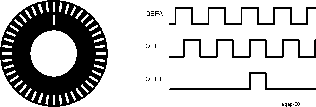 Figure 29-62 Optical Encoder Disk
To derive direction information, the lines on the disk are read out by two different photo-elements that "look" at the disk pattern with a mechanical shift of 1/4 the pitch of a line pair between them. This shift is realized with a reticle or mask that restricts the view of the photo-element to the desired part of the disk lines. As the disk rotates, the two photo-elements generate signals that are shifted 90 degrees out of phase from each other. These are commonly called the quadrature QEPA and QEPB signals. The clockwise direction for most encoders is defined as the QEPA channel going positive before the QEPB channel and vise versa as shown in Figure 29-63.
The encoder wheel typically makes one revolution for every revolution of the motor or the wheel may be at a geared rotation ratio with respect to the motor. Therefore, the frequency of the digital signal coming from the QEPA and QEPB outputs varies proportionally with the velocity of the motor. For example, a 2000-line encoder directly coupled to a motor running at 5000 revolutions per minute (rpm) results in a frequency of 166.6 KHz, so by measuring the frequency of either the QEPA or QEPB output, the processor can determine the velocity of the motor.
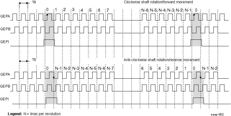 Figure 29-63 QEP Encoder Output Signal for Forward/Reverse Movement
Quadrature encoders from different manufacturers come with two forms of index pulse (gated index pulse or ungated index pulse) as shown in Figure 29-64. A nonstandard form of index pulse is ungated. In the ungated configuration, the index edges are not necessarily coincident with A and B signals. The gated index pulse is aligned to any of the four quadrature edges and width of the index pulse and can be equal to a quarter, half, or full period of the quadrature signal.
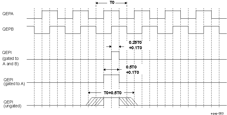 Figure 29-64 Index Pulse Example
Some typical applications of shaft encoders include robotics and even computer input in the form of a mouse. Inside your mouse you can see where the mouse ball spins a pair of axles (a left/right, and an up/down axle). These axles are connected to optical shaft encoders that effectively tell the computer how fast and in what direction the mouse is moving.
General Issues: Estimating velocity from a digital position sensor is a cost-effective strategy in motor control. Two different first order approximations for velocity may be written as:


where
v(k): Velocity at time instant k
x(k): Position at time instant k
x(k-1): Position at time instant k - 1
T: Fixed unit time or inverse of velocity calculation rate
ΔX: Incremental position movement in unit time
t(k): Time instant "k"
t(k-1): Time instant "k - 1"
X: Fixed unit position
ΔT: Incremental time elapsed for unit position movement.
Equation 8 is the conventional approach to velocity estimation and it requires a time base to provide unit time event for velocity calculation. Unit time is basically the inverse of the velocity calculation rate.
The encoder count (position) is read once during each unit time event. The quantity [x(k) - x(k-1)] is formed by subtracting the previous reading from the current reading. Then the velocity estimate is computed by multiplying by the known constant 1/T (where T is the constant time between unit time events and is known in advance).
Estimation based on Equation 8 has an inherent accuracy limit directly related to the resolution of the position sensor and the unit time period T. For example, consider a 500-line per revolution quadrature encoder with a velocity calculation rate of 400 Hz. When used for position the quadrature encoder gives a four-fold increase in resolution, in this case, 2000 counts per revolution. The minimum rotation that can be detected is therefore 0.0005 revolutions, which gives a velocity resolution of 12 rpm when sampled at 400 Hz. While this resolution may be satisfactory at moderate or high speeds, for example, 1% error at 1200 rpm, it would clearly prove inadequate at low speeds. In fact, at speeds below 12 rpm, the speed estimate would erroneously be zero much of the time.
At low speed, Equation 9 provides a more accurate approach. It requires a position sensor that outputs a fixed interval pulse train, such as the aforementioned quadrature encoder. The width of each pulse is defined by motor speed for a given sensor resolution. Equation 9 can be used to calculate motor speed by measuring the elapsed time between successive quadrature pulse edges. However, this method suffers from the opposite limitation, as does Equation 8. A combination of relatively large motor speeds and high sensor resolution makes the time interval ΔT small, and thus more greatly influenced by the timer resolution. This can introduce considerable error into high-speed estimates.
For systems with a large speed range (that is, speed estimation is needed at both low and high speeds), one approach is to use Equation 9 at low speed and have the software switch over to Equation 8 when the motor speed rises above some specified threshold.
29.4.2 eQEP Module Functional Description
This section provides the eQEP functional description and corrsponding functional details about EQEPx inputs .
Multiple identical eQEP modules can be contained in a system. For actual number of eQEP modules integrated in the device, refer to the Section 29.1.3. The letter x within a signal or module name is used to indicate a generic eQEP instance on a device. For example, output interrupt request, EQEP1A belongs to eQEP1, EQEP2A belongs to eQEP2, etc.
The eQEP peripheral contains the following major functional units (as shown in Figure 29-65):
- Programmable input qualification for each pin (part of the GPIO MUX)
- Quadrature decoder unit (QDU)
- Position counter and control unit for position measurement (PCCU)
- Quadrature edge-capture unit for low-speed measurement (QCAP)
- Unit time base for speed/frequency measurement (UTIME)
- Watchdog timer for detecting stalls (QWDOG)
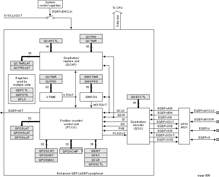 Figure 29-65 Functional Block Diagram of the eQEP Peripheral
29.4.3 eQEP Inputs
The eQEP inputs include two pins for quadrature-clock mode or direction-count mode, an index (or 0 marker), and a strobe input.
- QEPA/XCLK and QEPB/XDIR: These two pins can be used in quadrature-clock mode or direction-count mode.
- Quadrature-clock Mode: The eQEP encoders provide two square wave signals (A and B) 90 electrical degrees out of phase whose phase relationship is used to determine the direction of rotation of the input shaft and number of eQEP pulses from the index position to derive the relative position information. For forward or clockwise rotation, QEPA signal leads QEPB signal and vice versa. The quadrature decoder uses these two inputs to generate quadrature-clock and direction signals.
- Direction-count Mode: In direction-count mode, direction and clock signals are provided directly from the external source. Some position encoders have this type of output instead of quadrature output. The QEPA pin provides the clock input and the QEPB pin provides the direction input.
- QEPI: Index or Zero Marker: The eQEP encoder uses an index signal to assign an absolute start position from which position information is incrementally encoded using quadrature pulses. This pin is connected to the index output of the eQEP encoder to optionally reset the position counter for each revolution. This signal can be used to initialize or latch the position counter on the occurrence of a desired event on the index pin.
- QEPS: Strobe Input: This general-purpose strobe signal can initialize or latch the position counter on the occurrence of a desired event on the strobe pin. This signal is typically connected to a sensor or limit switch to notify that the motor has reached a defined position.
29.4.4 eQEP Quadrature Decoder Unit (QDU)
Figure 29-66 shows a functional block diagram of the QDU.
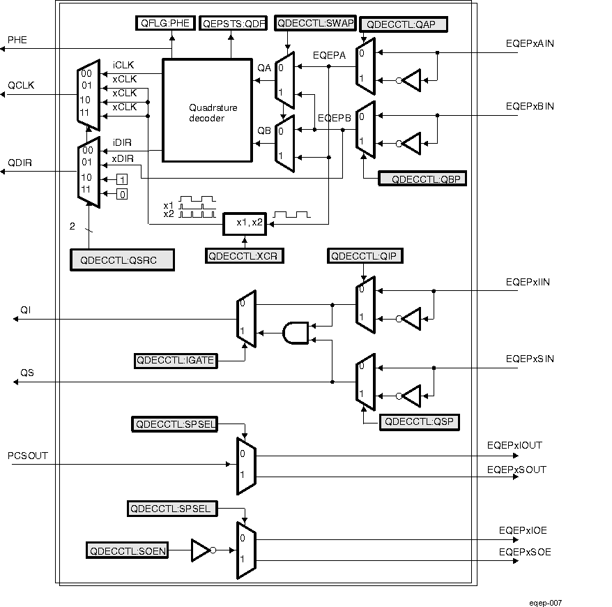 Figure 29-66 Functional Block Diagram of Decoder Unit
29.4.5 eQEP Position Counter Input Modes
Clock and direction input to position counter is selected using the QSRC bit in the eQEP decoder control register (EQEP_QDECCTL), based on interface input requirement as follows:
- Quadrature-count mode
- Direction-count mode
- UP-count mode
- DOWN-count mode
29.4.6 Quadrature Count Mode
The quadrature decoder generates the direction and clock to the position counter in quadrature count mode.
- Direction Decoding
The direction decoding logic of the eQEP circuit determines which one of the sequences (QEPA, QEPB) is the leading sequence and accordingly updates the direction information in the QDF bit in the eQEP status register (EQEP_QEPSTS). Table 29-140 and Figure 29-67 show the direction decoding logic in truth table and state machine form. Both edges of the QEPA and QEPB signals are sensed to generate count pulses for the position counter. Therefore, the frequency of the clock generated by the eQEP logic is four times that of each input sequence. Figure 29-68 shows the direction decoding and clock generation from the eQEP input signals.
- Phase Error Flag
In normal operating conditions, quadrature inputs QEPA and QEPB will be 90 degrees out of phase. The phase error flag (PHE) is set in the EQEP_QFLG register when edge transition is detected simultaneously on the QEPA and QEPB signals to optionally generate interrupts. State transitions marked by dashed lines in Figure 29-67 are invalid transitions that generate a phase error.
- Count Multiplication
The eQEP position counter provides 4x times the resolution of an input clock by generating a quadrature-clock (QCLK) on the rising/falling edges of both eQEP input clocks (QEPA and QEPB) as shown in Figure 29-68.
- Reverse Count
In normal quadrature count operation, QEPA input is fed to the QA input of the quadrature decoder and the QEPB input is fed to the QB input of the quadrature decoder. Reverse counting is enabled by setting the SWAP bit in the eQEP decoder control register (EQEP_QDECCTL). This will swap the input to the quadrature decoder thereby reversing the counting direction.
| Previous Edge | Present Edge | QDIR | QPOSCNT |
|---|---|---|---|
| QA↑ | QB↑ | UP | Increment |
| QB↓ | DOWN | Decrement | |
| QA↓ | TOGGLE | Increment or Decrement | |
| QA↓ | QB↓ | UP | Increment |
| QB↑ | DOWN | Decrement | |
| QA↑ | TOGGLE | Increment or Decrement | |
| QB↑ | QA↑ | DOWN | Increment |
| QA↓ | UP | Decrement | |
| QB↓ | TOGGLE | Increment or Decrement | |
| QB↓ | QA↓ | DOWN | Increment |
| QA↑ | UP | Decrement | |
| QB↑ | TOGGLE | Increment or Decrement |
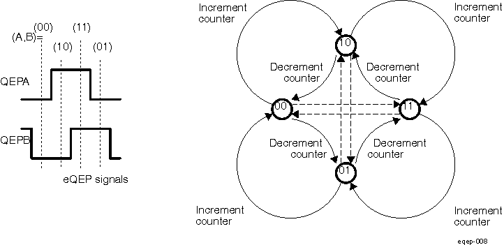 Figure 29-67 Quadrature Decoder State Machine
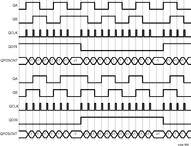 Figure 29-68 Quadrature-clock and Direction Decoding
29.4.7 eQEP Direction-count Mode
Some position encoders provide direction and clock outputs, instead of quadrature outputs. In such cases, direction-count mode can be used. QEPA input will provide the clock for position counter and the QEPB input will have the direction information. The position counter is incremented on every rising edge of a QEPA input when the direction input is high and decremented when the direction input is low.
29.4.8 eQEP Up-Count Mode
The counter direction signal is hard-wired for up count and the position counter is used to measure the frequency of the QEPA input. Setting of the XCR bit in the eQEP decoder control register (EQEP_QDECCTL) enables clock generation to the position counter on both edges of the QEPA input, thereby increasing the measurement resolution by 2× factor.
29.4.9 eQEP Down-Count Mode
The counter direction signal is hardwired for a down count and the position counter is used to measure the frequency of the QEPA input. Setting of the XCR bit in the eQEP decoder control register (EQEP_QDECCTL) enables clock generation to the position counter on both edges of a QEPA input, thereby increasing the measurement resolution by 2× factor.
29.4.10 eQEP Input Polarity Selection
Each eQEP input can be inverted using the in the eQEP decoder control register (EQEP_QDECCTL[8:5]) control bits. As an example, setting of the QIP bit in EQEP_QDECCTL inverts the index input.
29.4.11 eQEP Position-Compare Sync Output
The eQEP peripheral includes a position-compare unit that is used to generate the position-compare sync signal on compare match between the position counter register (EQEP_QPOSCNT) and the position-compare register (EQEP_QPOSCMP). This sync signal can be output using an index pin or strobe pin of the EQEP peripheral.
Setting the SOEN bit in the eQEP decoder control register (EQEP_QDECCTL) enables the position-compare sync output and the SPSEL bit in EQEP_QDECCTL selects either an eQEP index pin or an eQEP strobe pin.
29.4.12 eQEP Position Counter and Control Unit (PCCU)
The position counter and control unit provides two configuration registers (EQEP_QEPCTL and EQEP_QPOSCTL) for setting up position counter operational modes, position counter initialization/latch modes and position-compare logic for sync signal generation.
29.4.13 eQEP Position Counter Operating Modes
Position counter data may be captured in different manners. In some systems, the position counter is accumulated continuously for multiple revolutions and the position counter value provides the position information with respect to the known reference. An example of this is the quadrature encoder mounted on the motor controlling the print head in the printer. Here the position counter is reset by moving the print head to the home position and then position counter provides absolute position information with respect to home position.
In other systems, the position counter is reset on every revolution using index pulse and position counter provides rotor angle with respect to index pulse position.
Position counter can be configured to operate in following four modes
- Position Counter Reset on Index Event
- Position Counter Reset on Maximum Position
- Position Counter Reset on the first Index Event
- Position Counter Reset on Unit Time Out Event (Frequency Measurement)
In all the above operating modes, position counter is reset to 0 on overflow and to QPOSMAX bifield value in EQEP_QPOSMAX register on underflow. Overflow occurs when the position counter counts up after QPOSMAX value. Underflow occurs when position counter counts down after "0". Interrupt flag is set to indicate overflow/underflow in EQEP_QFLG register.
29.4.14 eQEP Position Counter Reset on Index Event (EQEP_QEPCTL[31:12] PCRM] = 0b00)
If the index event occurs during the forward movement, then position counter is reset to 0 on the next eQEP clock. If the index event occurs during the reverse movement, then the position counter is reset to the value in the EQEP_QPOSMAX register on the next eQEP clock.
First index marker is defined as the quadrature edge following the first index edge. The eQEP peripheral records the occurrence of the first index marker (EQEP_QEPSTS[FIMF]) and direction on the first index event marker (EQEP_QEPSTS[FIDF]) in EQEP_QEPSTS registers, it also remembers the quadrature edge on the first index marker so that same relative quadrature transition is used for index event reset operation.
For example, if the first reset operation occurs on the falling edge of QEPB during the forward direction, then all the subsequent reset must be aligned with the falling edge of QEPB for the forward rotation and on the rising edge of QEPB for the reverse rotation as shown in Figure 29-69.
The position-counter value is latched to the EQEP_QPOSILAT register and direction information is recorded in the EQEP_QEPSTS[QDLF] bit on every index event marker. The position-counter error flag (EQEP_QEPSTS[PCEF]) and error interrupt flag (EQEP_QFLG[PCE]) are set if the latched value is not equal to 0 or QPOSMAX. The position-counter error flag (EQEP_QEPSTS[PCEF]) is updated on every index event marker and an interrupt flag (EQEP_QFLG[PCE]) will be set on error that can be cleared only through software.
The index event latch configuration EQEP_QEPCTL[5:4] IEL bits are ignored in this mode and position counter error flag/interrupt flag are generated only in index event reset mode.
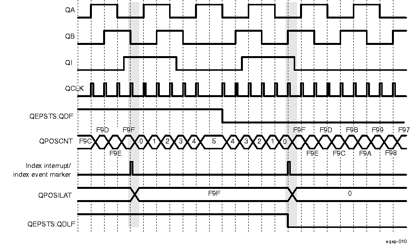 Figure 29-69 Position Counter Reset by Index Pulse for 1000 Line Encoder (QPOSMAX = 3999 or F9Fh)
29.4.15 eQEP Position Counter Reset on Maximum Position (EQEP_QEPCTL[13:12] PCRM=0b01)
If the position counter is equal to QPOSMAX (in EQEP_QPOSMAX register), then the position counter is reset to 0 on the next eQEP clock for forward movement and position counter overflow flag is set. If the position counter is equal to ZERO, then the position counter is reset to QPOSMAX on the next QEP clock for reverse movement and position counter underflow flag is set. Figure 29-70 shows the position counter reset operation in this mode.
First index marker is defined as the quadrature edge following the first index edge. The eQEP peripheral records the occurrence of the first index marker (EQEP_QEPSTS[FIMF]) and direction on the first index event marker (EQEP_QEPSTS[FIDF]) in the EQEP_QEPSTS registers; it also remembers the quadrature edge on the first index marker so that the same relative quadrature transition is used for the software index marker (EQEP_QEPCTL[5:4] IEL=0b11).
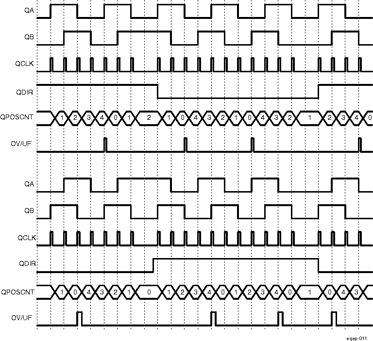 Figure 29-70 Position Counter Underflow/Overflow (QPOSMAX = 4)
29.4.16 Position Counter Reset on the First Index Event (EQEP_QEPCTL[13:12] PCRM = 0b10)
If the index event occurs during forward movement, then the position counter is reset to 0 on the next eQEP clock. If the index event occurs during the reverse movement, then the position counter is reset to the value in the EQEP_QPOSMAX register on the next eQEP clock. Note that this is done only on the first occurrence and subsequently the position counter value is not reset on an index event; rather, it is reset based on maximum position as described in Section 29.4.15.
First index marker is defined as the quadrature edge following the first index edge. The eQEP peripheral records the occurrence of the first index marker (EQEP_QEPSTS[FIMF]) and direction on the first index event marker (EQEP_QEPSTS[FIDF]) in EQEP_QEPSTS registers. It also remembers the quadrature edge on the first index marker so that same relative quadrature transition is used for software index marker (EQEP_QEPCTL[5:4] IEL= 0b11).
29.4.17 Position Counter Reset on Unit Time out Event (EQEP_QEPCTL[13:12] PCRM = 0b11)
In this mode, the QPOSCNT value is latched to the EQEP_QPOSLAT register and then the QPOSCNT field is reset (to 0 or the QPOSMAX value in the EQEP_QPOSMAX register, depending on the direction mode selected by EQEP_QDECCTL[QSRC] bits on a unit time event). This is useful for frequency measurement.
29.4.18 eQEP Position Counter Latch
The eQEP index and strobe input can be configured to latch the position counter QPOSCNT (EQEP_QPOSCNT) into QPOSILAT (EQEP_QPOSILAT register) and QPOSSLAT (EQEP_QPOSSLAT register) bitfields, respectively, on occurrence of a definite event on these pins.
29.4.19 Index Event Latch
In some applications, it may not be desirable to reset the position counter on every index event and instead it may be required to operate the position counter in full 32-bit mode (EQEP_QEPCTL[13:12] PCRM = 0b01 and EQEP_QEPCTL[13:12] PCRM = 0b10 modes).
In such cases, the eQEP position counter can be configured to latch on the following events and direction information is recorded in the EQEP_QEPSTS[QDLF] bit on every index event marker.
- Latch on Rising edge (EQEP_QEPCTL[5:4] IEL = 0b01)
- Latch on Falling edge (EQEP_QEPCTL[5:4] IEL = 0b10)
- Latch on Index Event Marker (EQEP_QEPCTL[5:4] IEL = 0b11)
This is particularly useful as an error checking mechanism to check if the position counter accumulated the correct number of counts between index events. As an example, the 1000-line encoder must count 4000 times when moving in the same direction between the index events.
The index event latch interrupt flag (EQEP_QFLG[IEL]) is set when the position counter is latched to the EQEP_QPOSILAT register. The index event latch configuration bits (QEPCTZ[IEL]) are ignored when EQEP_QEPCTL[13:12] PCRM = 0b00.
- Latch on Rising Edge (EQEP_QEPCTL[5:4] IEL = 0b01)
The position counter value (QPOSCNT) is latched to the EQEP_QPOSILAT register on every rising edge of an index input.
- Latch on Falling Edge (EQEP_QEPCTL[5:4] IEL = 0b10)
The position counter value (QPOSCNT) is latched to the EQEP_QPOSILAT register on every falling edge of index input.
- Latch on Index Event Marker/Software Index Marker (EQEP_QEPCTL[5:4] IEL = 0b11)
The first index marker is defined as the quadrature edge following the first index edge. The eQEP peripheral records the occurrence of the first index marker (EQEP_QEPSTS[FIMF]) and direction on the first index event marker (EQEP_QEPSTS[FIDF]) in the EQEP_QEPSTS registers. It also remembers the quadrature edge on the first index marker so that same relative quadrature transition is used for latching the position counter (EQEP_QEPCTL[5:4] IEL = 0b11).
Figure 29-71 shows the position counter latch using an index event marker.
![DRA742 DRA752 Software Index Marker for 1000-line Encoder (EQEP_QEPCTL[5:4] IEL = 0b01) DRA742 DRA752 Software Index Marker for 1000-line Encoder (EQEP_QEPCTL[5:4] IEL = 0b01)](/ods/images/SPRUI30H/GUID-A88E6061-EC66-49CD-80F7-D3C7DE1C160A-low.gif) Figure 29-71 Software Index Marker for 1000-line Encoder (EQEP_QEPCTL[5:4] IEL = 0b01)
Figure 29-71 Software Index Marker for 1000-line Encoder (EQEP_QEPCTL[5:4] IEL = 0b01)29.4.20 eQEP Strobe Event Latch
The position-counter value is latched to the EQEP_QPOSSLAT register on the rising edge of the strobe input by clearing the EQEP_QEPCTL[6] SEL bit.
If the EQEP_QEPCTL[6] SEL bit is set, then the position counter value is latched to the EQEP_QPOSSLAT register on the rising edge of the strobe input for forward direction and on the falling edge of the strobe input for reverse direction as shown in Figure 29-72.
The strobe event latch interrupt flag (EQEP_QFLG[SEL]) is set when the position counter is latched to the EQEP_QPOSSLAT register.
![DRA742 DRA752 eQEP Strobe Event Latch (EQEP_QEPCTL[6] SEL = 0b1) DRA742 DRA752 eQEP Strobe Event Latch (EQEP_QEPCTL[6] SEL = 0b1)](/ods/images/SPRUI30H/GUID-917011BE-A4C8-4374-A632-C8BBDF7C3742-low.gif) Figure 29-72 eQEP Strobe Event Latch (EQEP_QEPCTL[6] SEL = 0b1)
Figure 29-72 eQEP Strobe Event Latch (EQEP_QEPCTL[6] SEL = 0b1)29.4.21 eQEP Position Counter Initialization
The position counter can be initialized using following events:
- Index event
- Strobe event
- Software initialization
- Index Event Initialization (IEI)
The QEPI index input can be used to trigger the initialization of the position counter at the rising or falling edge of the index input.
If the EQEP_QEPCTL[9:8] IEI bits are 0b10, then the position counter (EQEP_QPOSCNT) is initialized with a value in the EQEP_QPOSINIT register on the rising edge of strobe input for forward direction and on the falling edge of strobe input for reverse direction.
The index event initialization interrupt flag (EQEP_QFLG[IEI]) is set when the position counter is initialized with a value in the EQEP_QPOSINIT register.
- Strobe Event Initialization (SEI)
If the EQEP_QEPCTL[11:10] SEI bits are 0b10, then the position counter is initialized with a value in the EQEP_QPOSINIT register on the rising edge of strobe input.
If the EQEP_QEPCTL[11:10] SEI bits are 0b11, then the position counter (EQEP_QPOSCNT) is initialized with a value in the EQEP_QPOSINIT register on the rising edge of strobe input for forward direction and on the falling edge of strobe input for reverse direction.
The strobe event initialization interrupt flag (EQEP_QFLG[SEI]) is set when the position counter is initialized with a value in the EQEP_QPOSINIT register.
- Software Initialization (SWI)
The position counter can be initialized in software by writing a '1' to the EQEP_QEPCTL[7] SWI bit, which will automatically be cleared after initialization.
29.4.22 eQEP Position-Compare Unit
The eQEP peripheral includes a position-compare unit that is used to generate a sync output and/or interrupt on a position-compare match. Figure 29-73 shows a diagram. The position-compare (EQEP_QPOSCMP) register is shadowed and shadow mode can be enabled or disabled using the EQEP_QPOSCTL[PSSHDW] bit. If the shadow mode is not enabled, the CPU writes directly to the active position compare register.
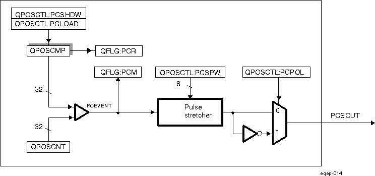 Figure 29-73 eQEP Position-compare Unit
In shadow mode, you can configure the position-compare unit (EQEP_QPOSCTL[PCLOAD]) to load the shadow register value into the active register on the following events and to generate the position-compare ready (EQEP_QFLG[PCR]) interrupt after loading.
- Load on compare match
- Load on position-counter zero event
The position-compare match (EQEP_QFLG[PCM]) is set when the position-counter value (QPOSCNT) matches with the active position-compare register (EQEP_QPOSCMP) and the position-compare sync output of the programmable pulse width is generated on compare match to trigger an external device.
For example, if EQEP_QPOSCMP bitfield QPOSCMP = 0x2, the position-compare unit generates a position-compare event on 1 to 2 transitions of the eQEP position counter for forward counting direction and on 3 to 2 transitions of the eQEP position counter for reverse counting direction (see Figure 29-74).
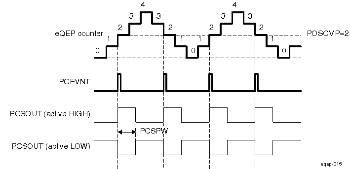 Figure 29-74 eQEP Position-compare Event Generation Points
The pulse stretcher logic in the position-compare unit generates a programmable position-compare sync pulse output on the position-compare match. In the event of a new position-compare match while a previous position-compare pulse is still active, then the pulse stretcher generates a pulse of specified duration from the new position-compare event as shown in Figure 29-75.
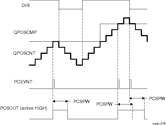 Figure 29-75 eQEP Position-compare Sync Output Pulse Stretcher
29.4.23 eQEP Edge Capture Unit
The eQEP peripheral includes an integrated edge capture unit to measure the elapsed time between the unit position events as shown in Figure 29-76. This feature is typically used for low speed measurement using the following equation:

where,
- X - Unit position is defined by integer multiple of quadrature edges (see Figure 29-77)
- ΔT - Elapsed time between unit position events
- v(k) - Velocity at time instant "k"
The eQEP capture timer (QCTMR bitfield in EQEP_QCTMR register) runs from prescaled SYSCLKOUT and the prescaler is programmed by the EQEP_QCAPCTL[CCPS] bits. The capture timer QCTMR value is latched into the capture period register (EQEP_QCPRD) on every unit position event and then the capture timer is reset, a flag is set in EQEP_QEPSTS[UPEVNT] to indicate that new value is latched into the EQEP_QCPRD register. Software can check this status flag before reading the period register for low speed measurement and clear the flag by writing 1.
The system clock - SYSCLKOUT is the eQEP functional clock derived from the PWMSSn gateable interface and functional clock PWMSSn_GICLK, described in Section 29.1.3.
Time measurement (ΔT) between unit position events will be correct if the following conditions are met:
- No more than 65,535 counts have occurred between unit position events.
- No direction change between unit position events.
The capture unit sets the eQEP overflow error flag (EQEP_QEPSTS[COEF]) in the event of capture timer overflow between unit position events. If a direction change occurs between the unit position events, then an error flag is set in the status register (EQEP_QEPSTS[CDEF]).
Capture Timer (EQEP_QCTMR register) and Capture period register (EQEP_QCPRD) can be configured to latch on following events.
- CPU read of EQEP_QPOSCNT register
- Unit time-out event
If the EQEP_QEPCTL[2] QCLM bit is cleared, then the capture timer and capture period values are latched into the EQEP_QCTMRLAT and EQEP_QCPRDLAT registers, respectively, when the CPU reads the position counter in EQEP_QPOSCNT.
If the EQEP_QEPCTL[2] QCLM bit is set, then the position counter, capture timer, and capture period values are latched into the EQEP_QPOSLAT, EQEP_QCTMRLAT and EQEP_QCPRDLAT registers, respectively, on unit time out.
Figure 29-78 shows the capture unit operation along with the position counter.
The EQEP_QCAPCTL register should not be modified dynamically (such as switching CAPCLK prescaling mode from QCLK/4 to QCLK/8). The capture unit must be disabled before changing the prescaler.
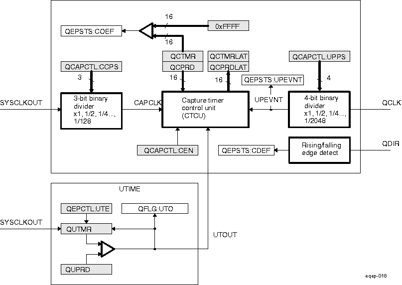 Figure 29-76 eQEP Edge Capture Unit
![DRA742 DRA752 Unit Position Event for Low Speed Measurement (EQEP_QCAPCTL[UPPS] = 0010) DRA742 DRA752 Unit Position Event for Low Speed Measurement (EQEP_QCAPCTL[UPPS] = 0010)](/ods/images/SPRUI30H/GUID-12A6EE0C-A02C-45A3-960A-98AE2C3F0E79-low.gif)
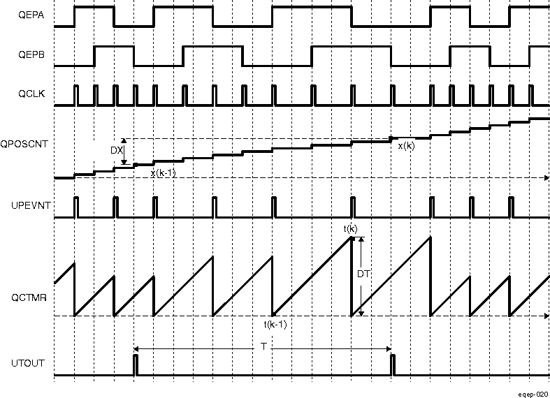 Figure 29-78 eQEP Edge Capture Unit - Timing Details
Velocity Calculation Equations:

where
v(k): Velocity at time instant k
x(k): Position at time instant k
x(k-1): Position at time instant k - 1
T: Fixed unit time or inverse of velocity calculation rate
ΔX: Incremental position movement in unit time
X: Fixed unit position
ΔT: Incremental time elapsed for unit position movement
t(k): Time instant "k"
t(k-1): Time instant "k - 1"
Unit time (T) and unit period (X) are configured using the EQEP_QUPRD and EQEP_QCAPCTL[UPPS] registers. Incremental position output and incremental time output is available in the EQEP_QPOSLAT and EQEP_QCPRDLAT registers.
| Parameter | Relevant Register to Configure or Read the Information |
|---|---|
| T | Unit Period Register (EQEP_QUPRD) |
| ΔX | Incremental Position = QPOSLAT(k) - QPOSLAT(K - 1) |
| X | Fixed unit position defined by sensor resolution and ZCAPCTL[UPPS] bits |
| ΔT | Capture Period Latch (QCPRDLAT) |
29.4.24 eQEP Watchdog
The eQEP peripheral contains a 16-bit watchdog timer that monitors the quadrature-clock to indicate proper operation of the motion-control system. The eQEP watchdog timer is clocked from SYSCLKOUT/64 and the quadrate clock event (pulse) resets the watchdog timer. If no quadrature-clock event is detected until a period match (QWDPRD = QWDTMR), then the watchdog timer will time out and the watchdog interrupt flag will be set (EQEP_QFLG[WTO]). The time-out value is programmable through the watchdog period register (EQEP_QWDPRD).
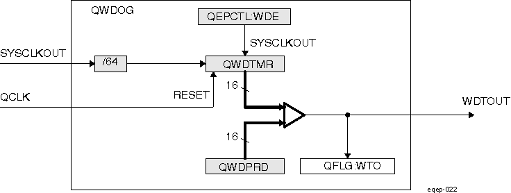 Figure 29-79 eQEP Watchdog Timer
29.4.25 Unit Timer Base
The eQEP peripheral includes a 32-bit timer (QUTMR) that is clocked by SYSCLKOUT to generate periodic interrupts for velocity calculations. The unit time out interrupt is set (EQEP_QFLG[UTO]) when the unit timer (QUTMR) matches the unit period register (EQEP_QUPRD).
The eQEP peripheral can be configured to latch the position counter, capture timer, and capture period values on a unit time out event so that latched values are used for velocity calculation as described in Section 29.4.23.
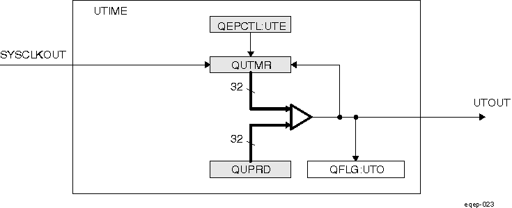 Figure 29-80 eQEP Unit Time Base
29.4.26 eQEP Interrupt Structure
Figure 29-81 shows how the interrupt mechanism works in the EQEP module.
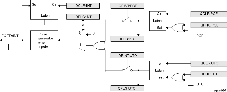 Figure 29-81 EQEP Interrupt Generation
Eleven interrupt events (PCE, PHE, QDC, WTO, PCU, PCO, PCR, PCM, SEL, IEL, and UTO) can be generated. The interrupt control register (EQEP_QEINT) is used to enable/disable individual interrupt event sources. The interrupt flag register (EQEP_QFLG) indicates if any interrupt event has been latched and contains the global interrupt flag bit (INT). An interrupt pulse is generated only to the interrupt controller if any of the interrupt events is enabled, the flag bit is 1 and the INT flag bit is 0. The interrupt service routine will need to clear the global interrupt flag bit and the serviced event, via the interrupt clear register (EQEP_QCLR), before any other interrupt pulses are generated. You can force an interrupt event by way of the interrupt force register (EQEP_QFRC), which is useful for test purposes.
29.4.27 Summary of PWMSS eQEP Functional Registers
Table 29-141 lists the registers with their memory locations, sizes, and reset values.
| Offset | Acronym | Register Description | Size(×16)/ #shadow |
|---|---|---|---|
| 0h | EQEP_QPOSCNT | eQEP Position Counter Register | 2/0 |
| 4h | EQEP_QPOSINIT | eQEP Position Counter Initialization Register | 2/0 |
| 8h | EQEP_QPOSMAX | eQEP Maximum Position Count Register | 2/0 |
| Ch | EQEP_QPOSCMP | eQEP Position-Compare Register | 2/1 |
| 10h | EQEP_QPOSILAT | eQEP Index Position Latch Register | 2/0 |
| 14h | EQEP_QPOSSLAT | eQEP Strobe Position Latch Register | 2/0 |
| 18h | EQEP_QPOSLAT | eQEP Position Counter Latch Register | 2/0 |
| 1Ch | EQEP_QUTMR | eQEP Unit Timer Register | 2/0 |
| 20h | EQEP_QUPRD | eQEP Unit Period Register | 2/0 |
| 24h | EQEP_QWDTMR | eQEP Watchdog Timer Register | 1/0 |
| 26h | EQEP_QWDPRD | eQEP Watchdog Period Register | 1/0 |
| 28h | EQEP_QDECCTL | eQEP Decoder Control Register | 1/0 |
| 2Ah | EQEP_QEPCTL | eQEP Control Register | 1/0 |
| 2Ch | EQEP_QCAPCTL | eQEP Capture Control Register | 1/0 |
| 2Eh | EQEP_QPOSCTL | eQEP Position-Compare Control Register | 1/0 |
| 30h | EQEP_QEINT | eQEP Interrupt Enable Register | 1/0 |
| 32h | EQEP_QFLG | eQEP Interrupt Flag Register | 1/0 |
| 34h | EQEP_QCLR | eQEP Interrupt Clear Register | 1/0 |
| 36h | EQEP_QFRC | eQEP Interrupt Force Register | 1/0 |
| 38h | EQEP_QEPSTS | eQEP Status Register | 1/0 |
| 3Ah | EQEP_QCTMR | eQEP Capture Timer Register | 1/0 |
| 3Ch | EQEP_QCPRD | eQEP Capture Period Register | 1/0 |
| 3Eh | EQEP_QCTMRLAT | eQEP Capture Timer Latch Register | 1/0 |
| 40h | EQEP_QCPRDLAT | eQEP Capture Period Latch Register | 1/0 |
| 5Ch | EQEP_REVID | eQEP Revision ID Register | 2/0 |
29.4.28 PWMSS_EQEP Register Manual
This section provides description of the PWMSS eQEP relevant functional registers.
29.4.29 PWMSS_EQEP Instance Summary
| Module Name | Module Base Address L4_PER2 Interconnect | Size (Bytes) |
|---|---|---|
| PWMSS1_EQEP | 0x4843 E180 | 116 Bytes |
| PWMSS2_EQEP | 0x4844 0180 | 116 Bytes |
| PWMSS3_EQEP | 0x4844 2180 | 116 Bytes |
29.4.30 PWMSS_EQEP Registers
29.4.31 PWMSS_EQEP Register Summary
| Register Name | Type | Register Width (Bits) | Address Offset | PWMSS1_EQEP Physical Address L4_PER2 Interconnect | PWMSS2_EQEP Physical Address L4_PER2 Interconnect | PWMSS3_EQEP Physical Address L4_PER2 Interconnect |
|---|---|---|---|---|---|---|
| EQEP_QPOSCNT | RW | 32 | 0x0 | 0x4843 E180 | 0x4844 0180 | 0x4844 2180 |
| EQEP_QPOSINIT | RW | 32 | 0x4 | 0x4843 E184 | 0x4844 0184 | 0x4844 2184 |
| EQEP_QPOSMAX | RW | 32 | 0x8 | 0x4843 E188 | 0x4844 0188 | 0x4844 2188 |
| EQEP_QPOSCMP | RW | 32 | 0xC | 0x4843 E18C | 0x4844 018C | 0x4844 218C |
| EQEP_QPOSILAT | R | 32 | 0x10 | 0x4843 E190 | 0x4844 0190 | 0x4844 2190 |
| EQEP_QPOSSLAT | R | 32 | 0x14 | 0x4843 E194 | 0x4844 0194 | 0x4844 2194 |
| EQEP_QPOSLAT | R | 32 | 0x18 | 0x4843 E198 | 0x4844 0198 | 0x4844 2198 |
| EQEP_QUTMR | RW | 32 | 0x1C | 0x4843 E19C | 0x4844 019C | 0x4844 219C |
| EQEP_QUPRD | RW | 32 | 0x20 | 0x4843 E1A0 | 0x4844 01A0 | 0x4844 21A0 |
| EQEP_QWDTMR | RW | 16 | 0x24 | 0x4843 E1A4 | 0x4844 01A4 | 0x4844 21A4 |
| EQEP_QWDPRD | RW | 16 | 0x26 | 0x4843 E1A6 | 0x4844 01A6 | 0x4844 21A6 |
| EQEP_QDECCTL | RW | 16 | 0x28 | 0x4843 E1A8 | 0x4844 01A8 | 0x4844 21A8 |
| EQEP_QEPCTL | RW | 16 | 0x2A | 0x4843 E1AA | 0x4844 01AA | 0x4844 21AA |
| EQEP_QCAPCTL | RW | 16 | 0x2C | 0x4843 E1AC | 0x4844 01AC | 0x4844 21AC |
| EQEP_QPOSCTL | RW | 16 | 0x2E | 0x4843 E1AE | 0x4844 01AE | 0x4844 21AE |
| EQEP_QEINT | RW | 16 | 0x30 | 0x4843 E1B0 | 0x4844 01B0 | 0x4844 21B0 |
| EQEP_QFLG | R | 16 | 0x32 | 0x4843 E1B2 | 0x4844 01B2 | 0x4844 21B2 |
| EQEP_QCLR | RW | 16 | 0x34 | 0x4843 E1B4 | 0x4844 01B4 | 0x4844 21B4 |
| EQEP_QFRC | RW | 16 | 0x36 | 0x4843 E1B6 | 0x4844 01B6 | 0x4844 21B6 |
| EQEP_QEPSTS | RW | 16 | 0x38 | 0x4843 E1B8 | 0x4844 01B8 | 0x4844 21B8 |
| EQEP_QCTMR | RW | 16 | 0x3A | 0x4843 E1BA | 0x4844 01BA | 0x4844 21BA |
| EQEP_QCPRD | RW | 16 | 0x3C | 0x4843 E1BC | 0x4844 01BC | 0x4844 21BC |
| EQEP_QCTMRLAT | R | 16 | 0x3E | 0x4843 E1BE | 0x4844 01BE | 0x4844 21BE |
| EQEP_QCPRDLAT | RW | 16 | 0x40 | 0x4843 E1C0 | 0x4844 01C0 | 0x4844 21C0 |
| EQEP_REVID | R | 32 | 0x5C | 0x4843 E1DC | 0x4844 01DC | 0x4844 21DC |
29.4.32 PWMSS_EQEP Register Description
| Address offset | 0x0 | ||||
| Physical Address | 0x4843 E180 0x4844 0180 0x4844 2180 | Instance | PWMSS1_EQEP PWMSS2_EQEP PWMSS3_EQEP | ||
| Description | |||||
| Type | RW | ||||
| 31 | 30 | 29 | 28 | 27 | 26 | 25 | 24 | 23 | 22 | 21 | 20 | 19 | 18 | 17 | 16 | 15 | 14 | 13 | 12 | 11 | 10 | 9 |