-
What Headlight Resolution Is High Enough for Symbol Projection? SSZT378 november 2019 DLP5531-Q1 , DLP5533A-Q1
-
What Headlight Resolution Is High Enough for Symbol Projection?
What Headlight Resolution Is High Enough for Symbol Projection?
Brandon Seiser
Trevor Dowd

Whether the application is your smartphone, your TV or your car’s headlights, having more pixels is usually better. These additional pixels increase the readability of small text and make small details visible on TVs.
New automotive headlight applications like adaptive driving beam (ADB) became available when technology advanced enough to allow 12 or more pixels per headlight. Now, DLP® technology enables carmakers to design cars with 1.3 million pixels per headlight. But what can you do with over 1 million pixels?
Automakers today need a lot of pixels in order to enable effective ADB, symbol projection and lane marking applications. However, not many technologies can accomplish all three applications today. One technology is TI DLP technology, which has developed a 0.55-inch diagonal digital micromirror device (DMD) designed with new advanced headlight applications in mind.
The DLP5531-Q1 is three times larger in active area than the first DMD designed for the automotive market (the DLP3030-Q1). The larger area supports three times more lumens than the DLP3030-Q1 (for a given illuminator source flux density) and triples achievable peak illuminance while using conventional LED light sources. The high temperature operating range includes operation at a die temperature of 105°C. The combination of higher temperature operation and a larger imager size helps support a broad headlight field of view (FOV).
Is 1.3 million pixels too many?
What applications require over 1 million pixels? On the surface, this amount of resolution seems like overkill, but in practice it’s actually not. To illustrate my point, let’s examine one example application: on-road augmented reality (AR)-style symbol projection.
To project images on a vertical surface such as a wall or garage door, resolution as low as 0.1 or 0.05 degrees per pixel is sufficient to create an interesting graphic symbol. Many demonstrations of these symbol projections exist in previous papers and conferences.
But what if the goal is not to display images on a wall, but rather to make the symbols appear to lie on the road’s surface, as if the symbol is painted on the road? If symbols were projected onto the road, automakers could design a visual communication system to help notify drivers of upcoming turns and better communicate with pedestrians.
For an image to appear as part of the road, one of the requirements is restricting the longitudinal length of the symbol on the road surface to a reasonable limit, say 2 to 3 m in length. Otherwise, the AR effect begins to get lost. Reducing the longitudinal length of the symbol reduces the vertical height of the symbol in angle space, which reduces the number of imager lines available to make the symbol.
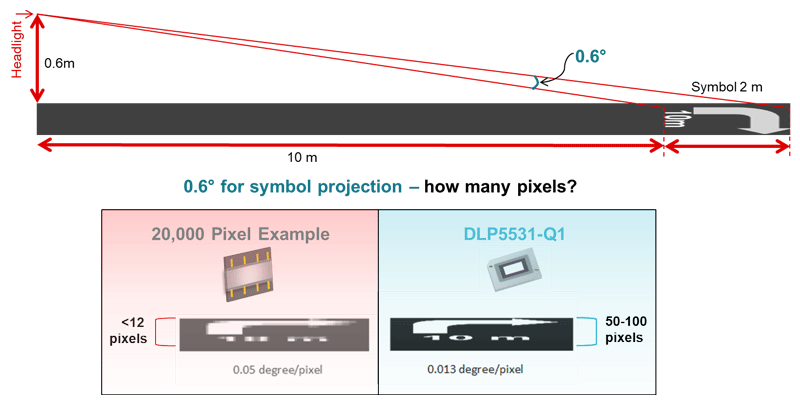
For example, when the imager’s maximum FOV is 7 degrees or more, the portion of the imager used for the symbol can be quite small in relation to the full FOV. The illustration in Figure 1 shows a 2-m-tall symbol at a relatively short distance of 10 m. The resulting height of the symbol in angle space is a mere 0.6 degrees. The calculation for the height of the symbol in angle space is shown in the top half of Figure 1.If the total vertical FOV is 7 degrees and the height of the image is the 0.6 degrees mentioned above, this means that the symbol must be constructed from only 8% to 10% of the available image vertical pixel lines. This 8% to 10% rapidly worsens if the distance from the car increases or the full FOV increases. If the image was projected to 20 m away from the car, the 2-m-tall image would occupy only about 0.16 degrees, or 2% of the available image vertical pixel lines.
 Figure 1 Pixel requirements for a 0.6° image height.
Figure 1 and the example above the figure shows respectable results with 0.013 degrees per pixel, but less-than-satisfactory results with 0.05 degrees per pixel. With just 0.05 degrees per pixel available, the 20,000-pixel system would require a taller symbol that covers several more meters of longitudinal road surface, which does not fit the AR definition. Even at a working distance of 10 m, we are able to see the value of having over one million pixels and are able to confirm that 1.3 million pixels are not too many.
Modulation transfer function
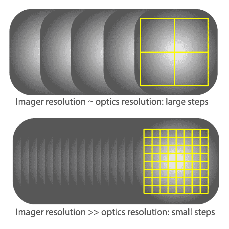
What is the advantage of having a rendering and imager resolution higher than the line pair resolving capability of the downstream projection optics? Line pair resolving capability is typically expressed as the modulation transfer function (MTF) of the projection optics. In systems with an optics MTF resolution lower than the imager’s pixel count limit, the optics set the minimum achievable feature size. But the object position adjustment resolution (and width/height step sizes above the minimum display size) is still governed by the imager resolution, as illustrated in Figure 2.
 Figure 2 Higher resolution gives precise control of motion and step size
The imager resolution affects how “smoothly” you can move and resize graphic objects such as masked areas around oncoming traffic. Using lower imager and rendering resolutions results in less natural motion, with discrete step sizes resulting in the appearance of motion judder. This judder effect is irrespective of the optical blurring caused by the limited MTF of the projection lens.
Conclusion
For a system using the DLP5531-Q1 0.55-in DMD operating in 1152-by-576 mode (half of native resolution) and a 7.5-degree full vertical FOV, the resulting vertical resolution is 0.013 degrees per pixel. For vertical FOV sizes significantly greater than 7.5 degrees, the 1152-by-1152 operating mode (native resolution) of the DMD is available and can double the effective vertical line resolution to maintain this level of performance. So even if you use the DMD for the entire traditional high-beam FOV plus symbol area, the 0.55-in DMD has the resolution required for on-road AR symbols.
Additional resources
- View the DLP auto headlight reference design using DLP technology.
- Learn more about the DLP5531-Q1 chipset in the training video, “DLP5531-Q1 chipset for headlight.”
- Read more about high-resolution ADB headlights in the technical article, “Create high-resolution adaptive headlights using DLP technology.”
IMPORTANT NOTICE AND DISCLAIMER
TI PROVIDES TECHNICAL AND RELIABILITY DATA (INCLUDING DATASHEETS), DESIGN RESOURCES (INCLUDING REFERENCE DESIGNS), APPLICATION OR OTHER DESIGN ADVICE, WEB TOOLS, SAFETY INFORMATION, AND OTHER RESOURCES “AS IS” AND WITH ALL FAULTS, AND DISCLAIMS ALL WARRANTIES, EXPRESS AND IMPLIED, INCLUDING WITHOUT LIMITATION ANY IMPLIED WARRANTIES OF MERCHANTABILITY, FITNESS FOR A PARTICULAR PURPOSE OR NON-INFRINGEMENT OF THIRD PARTY INTELLECTUAL PROPERTY RIGHTS.
These resources are intended for skilled developers designing with TI products. You are solely responsible for (1) selecting the appropriate TI products for your application, (2) designing, validating and testing your application, and (3) ensuring your application meets applicable standards, and any other safety, security, or other requirements. These resources are subject to change without notice. TI grants you permission to use these resources only for development of an application that uses the TI products described in the resource. Other reproduction and display of these resources is prohibited. No license is granted to any other TI intellectual property right or to any third party intellectual property right. TI disclaims responsibility for, and you will fully indemnify TI and its representatives against, any claims, damages, costs, losses, and liabilities arising out of your use of these resources.
TI’s products are provided subject to TI’s Terms of Sale (www.ti.com/legal/termsofsale.html) or other applicable terms available either on ti.com or provided in conjunction with such TI products. TI’s provision of these resources does not expand or otherwise alter TI’s applicable warranties or warranty disclaimers for TI products.
Mailing Address: Texas Instruments, Post Office Box 655303, Dallas, Texas 75265
Copyright © 2023, Texas Instruments Incorporated