SSZTBZ8 October 2015 TPS2511
Portable devices such as cellphones and tablets are capable of charging their batteries faster than ever. To obtain a fast charge time, the voltage at the charging device must be at the proper level. If it is not, the charger may reduce the charging current to a lower- (but still acceptable) level, ultimately extending the total charge time. Voltage droop across the charging cable can also cause inadequate voltage. Let’s take a look at how this might affect a universal serial bus (USB) cable and how to address potential problems.
A typical USB cable interface contact resistance is approximately 30mΩ. Since there are four connections (two on each cable end), this represents 0.12Ω. Assuming a standard 24AWG wire for each power line and a 1m cable length, the total wire resistance is 0.166Ω. The total expected cable and contact resistance is 0.286Ω. If the 5V converter is designed to provide a maximum output current of 2.1A, the expected voltage drop across the cable would be 0.6V. The voltage at the end of the cable would drop to 4.4V for a fixed-converter voltage of 5.0V. This is at the lower voltage limit for USB devices, so it’s easy to see how a high-current load can create potential issues. USB cables with heavier gauge wire may help, while extra-long USB cables, with smaller gauge wire, will charge below the maximum rate. Something must be done to increase charging currents further.
A common solution is to raise the output set voltage at no load, typically 5.0V, as high as possible, to 5.15V or 5.20V (5.25V maximum for USB 3.0). This solution provides adequate (although still minimal) headroom at a maximum 2.1A current. But for higher-load currents, this approach quickly runs out of steam.
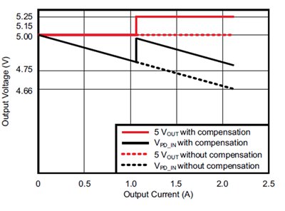
Another method involves using a dedicated charging port controller such as the TPS2511. This device monitors the USB data lines and automatically provides the correct electrical signatures to charge compliant devices; it also has a current-limiting function. Its current sense (/CS) pin pulls low when the output current is one-half the maximum set by a current-limiting threshold resistor. Connecting this pin through a resistor to the 5V power source’s feedback resistors (see Figure 33 in the TPS2511 data sheet) increases the output voltage, as shown in Figure 1. This reduces the voltage droop by about 50%. See the Dual-Port Automotive USB Charger Reference Design for an example design.
 Figure 1 Current Sensing Increases the
Output Voltage at 50% Load, Fighting Voltage Droop
Figure 1 Current Sensing Increases the
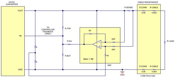
Output Voltage at 50% Load, Fighting Voltage DroopThe block diagram in Figure 2 details a method to linearly increase the converter’s output voltage to compensate for the cable losses, keeping the voltage at the end of the cable constant. This solution adds a sense resistor to monitor the output current. A differential amplifier increases the voltage across the sense resistor and uses this voltage to inject a current into the controller’s feedback (FB) pin. For more detail on this approach, see “Power Tips: Compensate for cable voltage droop”.
 Figure 2 Current Sensing Continuously
Adjusts the Feedback to Hold a Steady Voltage at the Load
Figure 2 Current Sensing Continuously
Adjusts the Feedback to Hold a Steady Voltage at the LoadThese techniques are just a few ways to fight voltage droop and get the fastest charge time possible.
Additional Resources
- Check out TI’s Power Tips blog series on Power House.
- For similar example designs, see Automotive USB Charger with Linear Droop Compensation Reference Design and Automotive USB Battery Charging Reference Design.