SWRA495K December 2015 – April 2024 CC1310 , CC1350 , CC2620 , CC2630 , CC2640 , CC2640R2F , CC2640R2F-Q1 , CC2642R-Q1 , CC2650 , CC2662R-Q1
- 1
- Abstract
- Trademarks
- 1Oscillator and Crystal Basics
- 2Overview of Crystal Oscillators for CC devices
- 3Selecting Crystals for the CC devices
- 4PCB Layout of the Crystal
- 5Measuring the Amplitude of the Oscillations of Your Crystal
- 6Crystals for CC13xx, CC26xx and CC23xx
- 7High Performance BAW Oscillator
- 8References
- 9Revision History
2.1 24-MHz and 48-MHz Crystal Oscillator
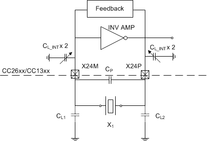
Figure 2-1 shows a simplified block diagram of the XOSC-HF. The oscillator circuit consists of an inverting amplifier, a feedback net, capacitors, and a crystal. The CC devices have an internal capacitor array that can be adjusted and eliminates the requirement for external loading capacitors. The cap-array can be adjusted by the Customer Configuration Flash (CCFG) within a range of 2 pF to 11 pF. For reliable operation, TI requires operating the crystal with CL from 5 to 9 pF. CC13xx/CC26xx Hardware Configuration and PCB Design Considerations shows how to set this value. If no external capacitors are used then the value of CL is determined by the internal loading capacitors plus board parasitic capacitance CP.
 Figure 2-1 Simplified Block Diagram
of the CC Devices High-Frequency Oscillator With Quartz Crystal
Figure 2-1 Simplified Block Diagram
of the CC Devices High-Frequency Oscillator With Quartz CrystalThe 24-MHz or 48-MHz crystal is controlled with a control loop described in Section 2.2 and Section 2.3.