SWRA577A October 2017 – November 2020 AWR1243 , AWR1443 , AWR1642 , AWR1843 , AWR1843AOP , AWR2243 , AWR6843 , IWR1443 , IWR1642 , IWR1843 , IWR6443 , IWR6843 , IWR6843AOP , LP87524B-Q1 , LP87524J-Q1
4.2.3 Spur/Noise Floor Level
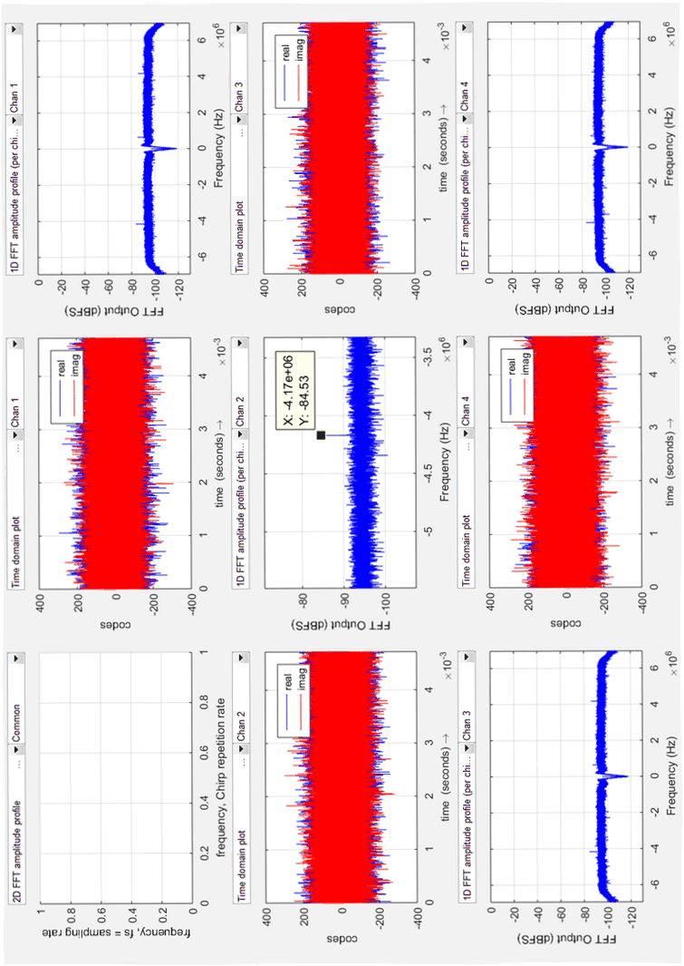
For Spur level measurements, a continuous tone at 77 GHz is transmitted and the received signal is analyzed with 524288 samples for the presence of the PMIC switching frequency spur at ~4 MHz. The Rx gain is set at 48dB with an observation that PMIC spur level tracks the Rx gain.
 Figure 4-6 LDO Scheme –Spur Level
Note:
No PMIC switching Frequency (approximately 4 MHz) Spur seen.
 Figure 4-7 LDO Scheme - Noise Floor With Tx –OFF
 Figure 4-8 LC Filter Scheme – Spur Level
Note:
PMIC spur is observed at -84.53 dBFS at RX gain of 48dB.
 Figure 4-9 LC Filter Scheme - Noise Floor With Tx –OFF