SWRA641A December 2018 – May 2021 CC1352P , CC1352R , CC2652P , CC2652R , CC2652R7 , CC2652RB , CC2652RSIP
Application Brief
Connectivity solutions continue to be widely adopted for sensing and monitoring in applications like Building Security and HVAC systems. A growing trend in these industries is to leverage multiple wireless technologies to enhance and expand applications by capitalizing on the unique benefits of different wireless standards such as Bluetooth® Low Energy for smartphone connectivity, Zigbee® for mesh, Sub-1 GHz for long range and low power. The Texas Instruments™SimpleLink™ platform has the hardware to support these applications along with a software module called the Dynamic Multi-protocol Manager (DMM).
Traditionally, supporting two wireless protocols would require a two-chip design which can increase board size and expenses for designers. Without DMM, a single chip cannot operate two protocols at the same time and must bootload a new firmware image when it needs to switch between them.
Texas Instruments™ single-chip, multi-standard solution supported by the DMM is not only cost-effective, but also simplifies multi-protocol design. With the SimpleLink CC1352 and CC2652 MCUs, users can leverage a single wireless MCU and support multiple different wireless standards. For example, a multi-band device like the SimpleLink CC1352 MCU can support concurrent operation of Bluetooth Low Energy and Sub-1 GHz by leveraging the DMM.
What is DMM?
The DMM is a software module that enables a single radio to operate multiple wireless protocols concurrently by switching between them in real time. This is also known as “Time Multiplexing”, in which the radio switches between the two protocol stacks by changing the settings, channels, and other parameters. The DMM will potentially modify the order in which RF commands are scheduled based on the constraints of the protocol stacks and the user application.
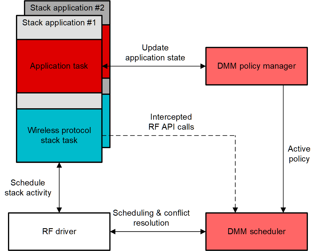
Figure 1-1 is a visual of the overall architecture of the DMM.
The DMM consists of two primary components: the policy manager and the scheduler. The policy manager includes a global priority table (GPT) and policy table. These help it know the current state of each stack application as well as what scheduling parameters to use for a specific combination of application states.
The DMM scheduler is as a single component in the application. It keeps track of RF commands submitted by each stack and PHY switching events originating in the RF driver. The scheduler gets information from the policy manager on how to perform scheduling of the associated stacks. When a stack schedules an RF command, a stack activity and priority level is provided with the scheduled RF command as part of the schedule parameters. If there is a conflict with another command at the scheduled start time, the conflict is resolved based on the current policy.
For example, the policy table can give higher priority to the Sub-1 GHz stack, causing the scheduler to preempt the Bluetooth Low Energy task when there is an immediate need for the Sub-1 GHz state. Table 1-1 is an example of a simplified policy table for that instance, in which the Sub-1 GHz sensor uses the TI 15.4 SimpleLink Sub-1 GHz stack solution.
 Figure 1-1 DMM Architecture
| Stack Type | Bluetooth Low Energy Peripheral | TI 15.4 Sensor |
|---|---|---|
| Stack state | Advertising + Connected | Connected |
| Policy | Low Priority, Not Time Critical, Policy Not Paused | High Priority, Not Time Critical, Policy Not Paused |
 Figure 1-2 DMM Scheduler Preemption Due
to Policy Table Priority
Figure 1-2 DMM Scheduler Preemption Due
to Policy Table PrioritySmart E-Lock: Sub-1 GHz + Bluetooth Low Energy
Electronic Door Locks in apartments or hotel buildings often require tedious maintenance and installation. Sub-1 GHz technology enables convenient control of a system of e-locks without the hassle or cost of wires. By integrating Bluetooth Low Energy into this system, designers can add a convenient user interface to a phone that can be used to install or control the system. The interface can potentially provide information about battery life of individual locks, status of the network, and even unlock or lock doors remotely. This can only be done concurrently on a single chip by using the DMM software module, which will allow the Sub-1 GHz stack to work simultaneously with the Bluetooth network.
 Figure 1-3 Sub-1 GHz Communication
Scheduled Between Bluetooth Low Energy Connection Events
Figure 1-3 Sub-1 GHz Communication
Scheduled Between Bluetooth Low Energy Connection EventsIn a
Bluetooth Low Energy system, there is a central (master) role and a peripheral
(slave) role, in which they meet at periodic “connection events” to exchange data.
Currently, TI supports a DMM solution that uses a Sub-1 GHz sensor with a Bluetooth
Low Energy Peripheral. For this E-lock solution, the mobile device (as a Bluetooth
Low Energy central device) can communicate with the Bluetooth Low Energy peripheral
on connection events, and can send updates on the Sub-1 GHz network. The Sub-1 GHz
communications are asynchronous, and they will most likely be scheduled between
Bluetooth Low Energy connection events. In case of conflict, priority will typically
be given to the
Sub-1 GHz.
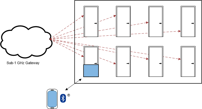
Figure 1-4 is a visual building automation example for electronic door locks connected to a gateway by way of the Sub-1 GHz, and an individual phone connected to a door lock through Bluetooth Low Energy.
 Figure 1-4 Building Automation Example
for Electronic Door Locks
Figure 1-4 Building Automation Example
for Electronic Door LocksA Zigbee and Bluetooth Low Energy door lock system will function similarly for the Electronic Door Lock use case. A phone can connect to a Zigbee router through Bluetooth Low Energy, and the router will connect to the rest of the Zigbee network. The device will default to stay in the Zigbee mode, and switch to Bluetooth Low Energy during those specific events. In case of a priority conflict, Bluetooth Low Energy is typically given priority.
Get Started
The DMM is part of the SimpleLink
ecosystem, which simplifies code migration for all SimpleLink devices. Interactive
training through the SimpleLink™ Academy provides multi-protocol demos and
examples for Dynamic Multi-protocol solutions, Over-The-Air Download (OAD), and
“Switching”
Multi-protocol solutions.
Learn more about the SimpleLink™ MCU platform and get started on building your DMM solution with the SimpleLink Academy DMM Fundamentals Guide.
References