SWRA734 December 2021 CC1312PSIP , CC1312R , CC1312R7 , CC1314R10 , CC1352P , CC1352P7 , CC1352R , CC1354P10 , CC1354R10 , CC2652P , CC2652P7 , CC2652R , CC2652RB , CC2652RSIP
6.2 PAN Coordinator Switching Due to a Command Coming From the Central Gateway
This coordinator switching scenario requires a modification to both the sensor and the collector examples. Even though some of the steps are common to both the sensor and the collector, a separate list of steps is provided for each example project.
To keep the implementation simple, instead of relying of a message coming from a central gateway, the CUI of the collector example is modified to add a new type of user action, and it is the user the one that initiates the coordinator switching process by selecting the correct option in the CUI. By picking this option, the PAN coordinator sends a new type of message to the sensor device which process and uses the information in it to switch to a different PAN coordinator.
First steps are common for both the sensor and the collector examples:
- Import the following example projects into the IDE workspace:
- TI 15.4-Stack Sensor project
- TI 15.4-Stack Collector project (used as original collector)
- TI 15.4-Stack Collector project (used as replacement collector)
Note: To differentiate the collectors when using the Common User Interface (CUI), modify the SFF_MENU_TITLE macro in csf.c, so that each project is properly identified. - Configure the sensor and collector projects so that they operate in the same mode, and with the same PHY. Also consider the following:
- The PAN ID field for the sensor should be set as 0xFFFF.
- Each collector device should use a different PAN ID.
- Each collector device should use a different channel mask.
- The sensor device should use a channel mask that covers the channels at which both collectors operate.
- Use different short addresses for each coordinator. The short address can be modified in the file advanced_config.h.
The following steps are the changes to the sensor project:
- Open the smsgs.h file, and add two new message types to the Constants and definitions section. One for the request (sent by the coordinator) and one for the reply (sent by the
sensor).
/****************************************************************************** Constants and definitions *****************************************************************************/ /*! Switch Collector Request message length (over-the-air length) */ #define SMSGS_SWITCH_COLLECTOR_REQUEST_MSG_LEN 3 /*! Switch Collector Response message length (over-the-air length) */ #define SMSGS_SWITCH_COLLECTOR_RESPONSE_MSG_LEN 2 /*! Message IDs for Sensor data messages. When sent over-the-air in a message, this field is one byte. */ typedef enum { // Existing message types /* Switch collector message, sent from the collector to the sensor */ Smsgs_cmdIds_switchCollectorReq = 18, /* Switch collector response msg, sent from the sensor to the collector */ Smsgs_cmdIds_switchCollectorRsp = 19 } Smsgs_cmdIds_t; /****************************************************************************** Structures - Building blocks for the over-the-air sensor messages *****************************************************************************/ // Existing structures in the example /*! Switch collector Request message: sent from controller to the sensor. */ typedef struct _Smsgs_switchcollectorreqmsg_t { /*! Command ID - 1 byte */ Smsgs_cmdIds_t cmdId; /*! PAN ID of replacement coordinator - 2 bytes */ uint16_t switchPanId; } Smsgs_switchCollectorReqMsg_t; /*! Switch collector Response message: sent from the sensor to the collector in response to the Switch collector Request message. */ typedef struct _Smsgs_switchcollectorrspmsg_t { /*! Command ID - 1 byte */ Smsgs_cmdIds_t cmdId; /*! Acknowledge from the sensor - 1 byte */ uint8_t sensorAck; } Smsgs_switchCollectorRspMsg_t; - Open the file sensor.c and add a function prototype of the function that will be used to trigger the coordinator switching.
static void processCoordinatorSwitchMsg(ApiMac_mcpsDataInd_t *pDataInd); - In sensor.c, add the following global variable:
extern bool switchCoordinatorFlag; - In sensor.c, define the local function used to trigger the coordinator switch:
static void processCoordinatorSwitchMsg(ApiMac_mcpsDataInd_t *pDataInd) { uint8_t *pBuf = pDataInd->msdu.p; switchCoordinatorFlag = true; newCoordinatorPanId = Util_buildUint16(pBuf[1], pBuf[2]); Jdllc_sendDisassociationRequest(); } - In sensor.c, modify the data indication callback to consider the new type of message previously defined:
static void dataIndCB(ApiMac_mcpsDataInd_t *pDataInd) { // Existing code in the example switch(cmdId) { // Existing code in the example case Smsgs_cmdIds_switchCollectorReq: /* Make sure the message is the correct size */ if(pDataInd->msdu.len == SMSGS_SWITCH_COLLECTOR_REQUEST_MSG_LEN) { /* only send data if sensor is in the network */ if ((Jdllc_getProvState() == Jdllc_states_joined) || (Jdllc_getProvState() == Jdllc_states_rejoined)) { /* send the response message directly */ cmdBytes[0] = (uint8_t) Smsgs_cmdIds_switchCollectorRsp; cmdBytes[1] = true; Sensor_sendMsg(Smsgs_cmdIds_switchCollectorRsp, &pDataInd->srcAddr, true, SMSGS_SWITCH_COLLECTOR_RESPONSE_MSG_LEN, cmdBytes); processCoordinatorSwitchMsg(pDataInd); } } break; - Open the file jdllc.c and add the following global variable:
bool switchCoordinatorFlag = false; uint16_t replacementCoordinatorPanId = 0xFFFF; - In jdllc.c, modify the disassociate confirm callback to check switchCoordinatorFlag and act accordingly.
static void disassoCnfCb(ApiMac_mlmeDisassociateCnf_t *pData) { // Existing code in the example if(switchCoordinatorFlag) { /* We need to return this flag to false, since we'll be * connecting to a new PAN ID. */ panIdMatch = false; abandonNetwork(); if(CONFIG_MAC_BEACON_ORDER == JDLLC_BEACON_ORDER_NON_BEACON) { /* non beacon network */ sendScanReq(ApiMac_scantype_active); } else if((CONFIG_MAC_BEACON_ORDER > 0) && (CONFIG_MAC_BEACON_ORDER < JDLLC_BEACON_ORDER_NON_BEACON)) { /* beacon network */ updateState(Jdllc_states_joining); sendScanReq(ApiMac_scantype_passive); } switchCoordinatorFlag = false; } - In jdllc.c, modify the beacon notification callback so that the sensor only connects to the appropriate the PAN coordinator.
static void beaconNotifyIndCb(ApiMac_mlmeBeaconNotifyInd_t *pData)
{
    /* check beacon type */
    if(pData->beaconType == ApiMac_beaconType_normal)
    {
        if(parentFound == false)
        {
            /* Check if association bit permit is set */
            if(APIMAC_SFS_ASSOCIATION_PERMIT(pData->panDesc.superframeSpec))
            {
                /* Check for beacon order match */
                if(checkBeaconOrder(pData->panDesc.superframeSpec) == true)
                {
                    if(devInfoBlock.panID == JDLLC_INVALID_PAN)
                    {
                        /* Device can join any network, associate with
                         * first coordinator from which beacon is received */
                        devInfoBlock.panID = pData->panDesc.coordPanId;
                        panIdMatch = true;
                        devInfoBlock.channel = pData->panDesc.logicalChannel;
                        devInfoBlock.coordShortAddr = pData->panDesc
                                        .coordAddress.addr.shortAddr;
                    }
                    /* Check the incoming PAN ID to see if it's a valid coordinator */
                    else if (devInfoBlock.panID == pData->panDesc.coordPanId)
                    {
                        panIdMatch = true;
                        numSyncLoss = 0;
                        ApiMac_mlmeSetReqBool(ApiMac_attribute_autoRequest, true);
                        devInfoBlock.channel = pData->panDesc.logicalChannel;
                        devInfoBlock.coordShortAddr = pData->panDesc
                                        .coordAddress.addr.shortAddr;
                    }
                    if(APIMAC_SFS_BEACON_ORDER( pData->panDesc.superframeSpec)
                                    != JDLLC_BEACON_ORDER_NON_BEACON)
                    {
                        devInfoBlock.beaconOrder = APIMAC_SFS_BEACON_ORDER(
                                        pData->panDesc.superframeSpec);
                        devInfoBlock.superframeOrder =
                            APIMAC_SFS_SUPERFRAME_ORDER(pData->panDesc.superframeSpec);
                    }
                    if((devInfoBlock.beaconOrder == JDLLC_BEACON_ORDER_NON_BEACON)
                        && (panIdMatch == true))
                    {
                        parentFound = true;
                        Ssf_stopScanBackoffClock();
                    }
                }
            }
        }
    }
    // Existing code
}
The following steps are the changes to the collector projects:
- Repeat step (3) for the collector projects.
- Open collector.h and declare a function to send the coordinator switch request message.
extern Collector_status_t Collector_sendCollectorSwitchRequest( ApiMac_sAddr_t *pDstAddr); - Open collector.c and add the definition for the previously declared function:
Collector_status_t Collector_sendCollectorSwitchRequest(ApiMac_sAddr_t *pDstAddr)
{
    Collector_status_t status = Collector_status_invalid_state;

    /* A hard-coded value is used for simplicity. In a real implementation
     * the gateway should inform the coordinator about the approved PAN ID
     * for the switch.
     * Use the appropriate value depending on which collector project is
     * being modified.
     */
    uint16_t newPanId = 0x1234;

    /* Are we in the right state? */
    if(cllcState >= Cllc_states_started)
    {
        Llc_deviceListItem_t item;

        /* Is the device a known device? */
        if(Csf_getDevice(pDstAddr, &item))
        {
            uint8_t msgBuf[SMSGS_SWITCH_COLLECTOR_REQUEST_MSG_LEN];
            uint8_t *pBuf = msgBuf;

            /* Build the message */
            *pBuf++ = (uint8_t) Smsgs_cmdIds_ switchCollectorReq;
            pBuf = Util_bufferUint16(pBuf, newPanId);

            sendMsg(Smsgs_cmdIds_switchCollectorReq, item.devInfo.shortAddress,
                    item.capInfo.rxOnWhenIdle,
                    SMSGS_SWITCH_COLLECTOR_REQUEST_MSG_LEN,
                    buffer);

            status = Collector_status_success;
        }
        else
        {
            status = Collector_status_deviceNotFound;
        }
    }
    return(status);
}
Note: If the suggested changes are implemented on both collector projects, make sure to set the appropriate value for the newPanId variable. - Open collector.c and add a local function prototype for the processing of the response coming from the sensor:
static void processCollectorSwitchResponse(ApiMac_mcpsDataInd_t *pDataInd); - In collector.c, also add the function necessary to process the response coming from the sensor.
static void processCollectorSwitchResponse(ApiMac_mcpsDataInd_t *pDataInd) { /* Make sure the message is the correct size */ if(pDataInd->msdu.len == SMSGS_SWITCH_COLLECTOR_RESPONSE_MSG_LEN) { // Add necessary code to send message to Gateway } } - Open csf.h, and add a constant for the coordinator switch action that will trigger the switching process.
#define SENSOR_ACTION_SWITCH 4 - In csf.h, declare a function that will be used to indicate that a sensor device has responded to the coordinator switch command.
extern void Csf_switchResponseReceived(ApiMac_sAddr_t *pSrcAddr, bool switchState); - In csf.c, declare a local function. One will be used as a response to an action coming from the CUI, and the other one will be used to update the CUI about the status of the request.
static void sensorCollectorSwitchAction(int32_t menuEntryInex); static void sendCollectorSwitchAndUpdateUser(uint16_t shortAddr); - In csf.c, define the previously mentioned functions:
static void sensorCollectorSwitchAction(int32_t menuEntryInex) { Csf_events |= COLLECTOR_SENSOR_ACTION_EVT; Csf_sensorAction = SENSOR_ACTION_SWITCH; // Wake up the application thread when it waits for clock event Semaphore_post(collectorSem); } void Csf_switchResponseReceived(ApiMac_sAddr_t *pSrcAddr, bool switchState) { /* This is an optional function used to visually notify the user that the sensor * has acknowledged the coordinator switch. For example, toggle a LED. */ } static void sendCollectorSwitchAndUpdateUser(uint16_t shortAddr) { { ApiMac_sAddr_t recipientDev; recipientDev.addr.shortAddr = shortAddr; if(recipientDev.addr.shortAddr != CSF_INVALID_SHORT_ADDR) { recipientDev.addrMode = ApiMac_addrType_short; Collector_sendCollectorSwitchRequest(&recipientDev); #ifndef CUI_DISABLE CUI_statusLinePrintf(csfCuiHndl, deviceStatusLine, "Switch Collector Request Sent - Addr=0x%04x", recipientDev.addr.shortAddr); #endif /* CUI_DISABLE */ } } } - In csf.c, add a menu item to the CUI that will show inside the APP submenu. Do this by first modifying the number items from five to six, and by adding the item with its associated
callback.
CUI_SUB_MENU(appSubMenu,"< APP >", 6, csfMainMenu) // Value was originally 5 CUI_MENU_ITEM_ACTION("< SWITCH COLLECTOR >", sensorCollectorSwitchAction) - In csf.c, add the appropriate case to the CSf_processEvents() function:
void Csf_processEvents(void) { /* Did a key press occur? if(Csf_events & CSF_KEY_EVENT) { // Existing code in the example } // Existing code in the example if(Csf_events & COLLECTOR_SENSOR_ACTION_EVT) { // Existing code in the example switch(Csf_sensorAction) { // Existing code in the example case SENSOR_ACTION_SWITCH: { /* send Collector Switch if CUI */ sendCollectorSwitchAndUpdateUser(SelectedSensor); break; } // Existing code in the example } } - Build the projects, make sure that there are no build errors, and flash the modified sensor and collector examples.
- Start the collectors, set their join permit to ON, and start the sensor so that it connects to one of the collectors.
- Set up the packet sniffers using the same steps as before, and verify the packet exchange in Wireshark.
- Using the keyboard, navigate the CUI of the collector that is connected to sensor. First go to the APP submenu, and then go to the “SWITCH COLLECTOR” item.
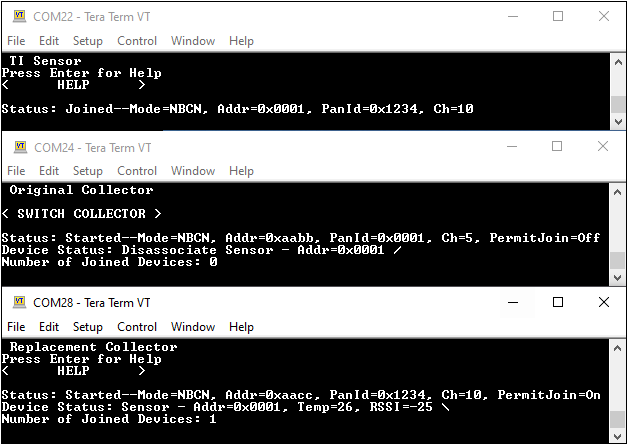
- Press the ENTER key to trigger the coordinator switching. Verify that the process is successful with Wireshark and with the CUIs of the examples.
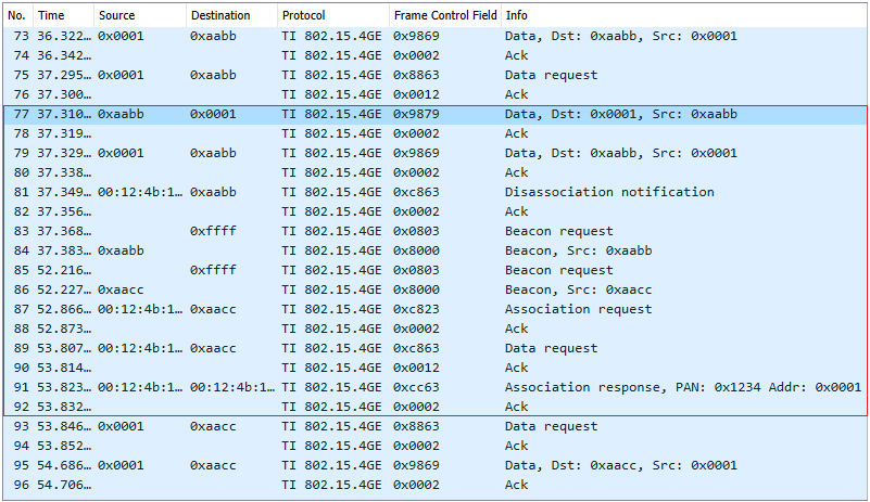
 Figure 6-9 Packet Exchange Showing the Sensor Switching PAN Coordinators
Messages 73 to 76 correspond to a normal message exchange between the sensor and its original PAN coordinator (with short address 0xaabb). Message 77 corresponds to the message sent by the original PAN coordinator indicating the sensor to switch to a different PAN coordinator. This message is sent when the user interacts with the CUI.
The message is acknowledged, and then a reply message is sent by the sensor (messages 78 and 79). This is followed by a disassociation notification sent by the sensor (message 81) and a beacon request to which both collectors reply. Notice that the original PAN coordinator also replies to the beacon request sent by the sensor. The sensor then makes an association request to the replacement coordinator (with short address 0xaacc) and once this succeeds, communication resumes.
 Figure 6-10 Common User Interface for the Sensor and Two Collectors After the First Collector Sends a Switching Coordinator Request