TIDUEP1A April 2019 – April 2020
3.2.1 Test Setup
This subsection provides details of the test setup with the required hardware and software to run the gesture-based HMI application.
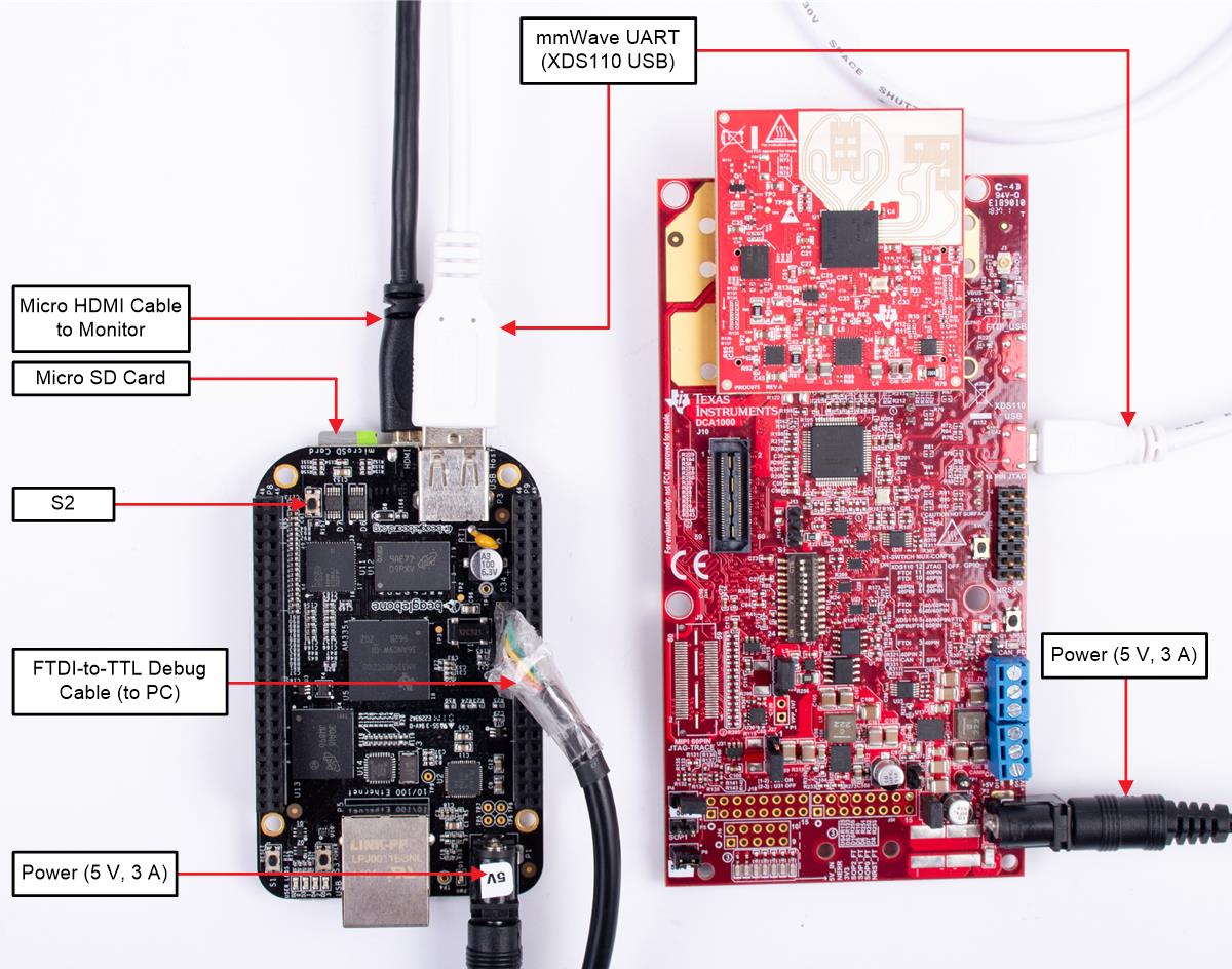
Figure 10. TIDEP01013 Gesture HMI Hardware Setup

- Follow the instructions provided in the multi_gesture_and _motion_detection lab user's guide (downloaded in Section 3.1.2.2) to setup the IWR6843 mmWave sensor EVM and flash the lab binary onto it.
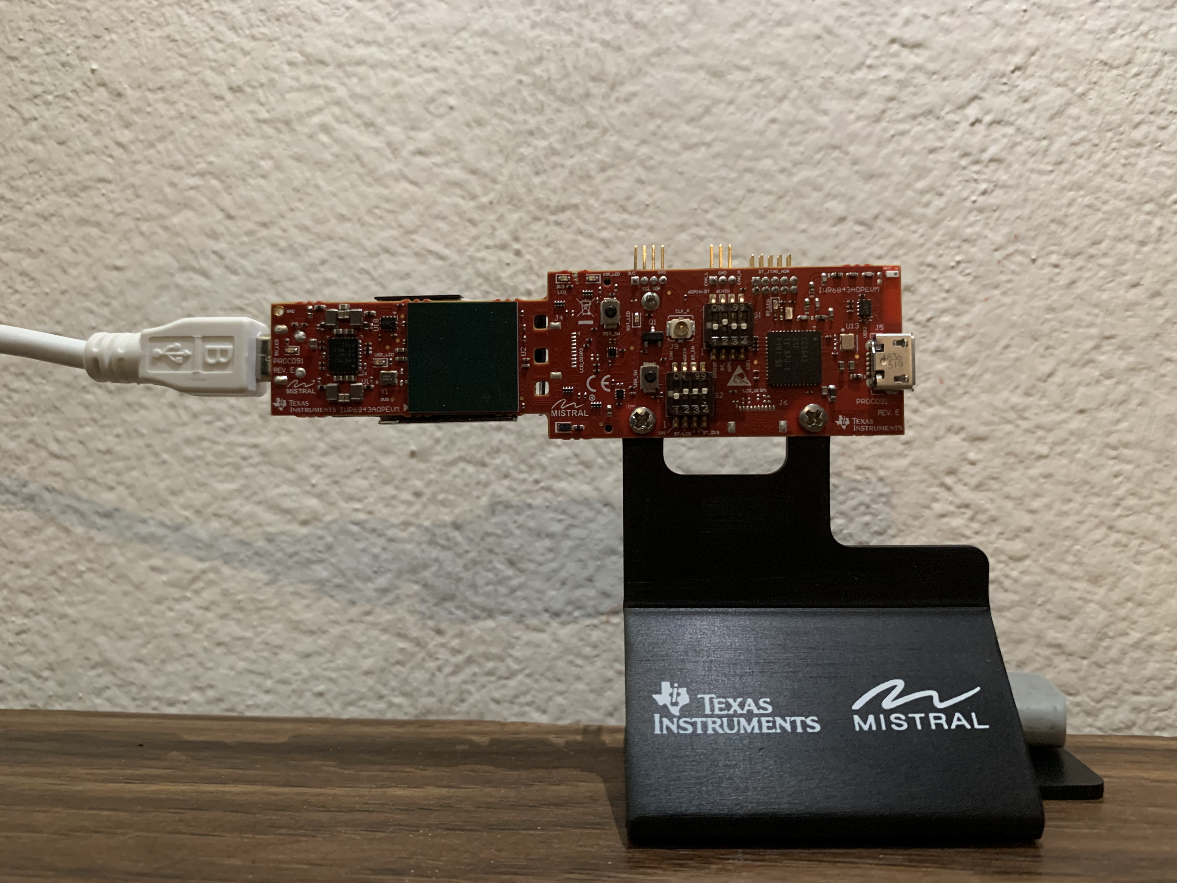
- Mount the mmWave EVM in the orientation shown in (see Figure 9).
- Follow the instructions outlined in Section 3.1.2.1, AM335x BBB to create a bootable microSD card with PLSDK image for the BBB.
- Insert the now bootable microSD card into the BBB microSD card slot. (see Figure 10).
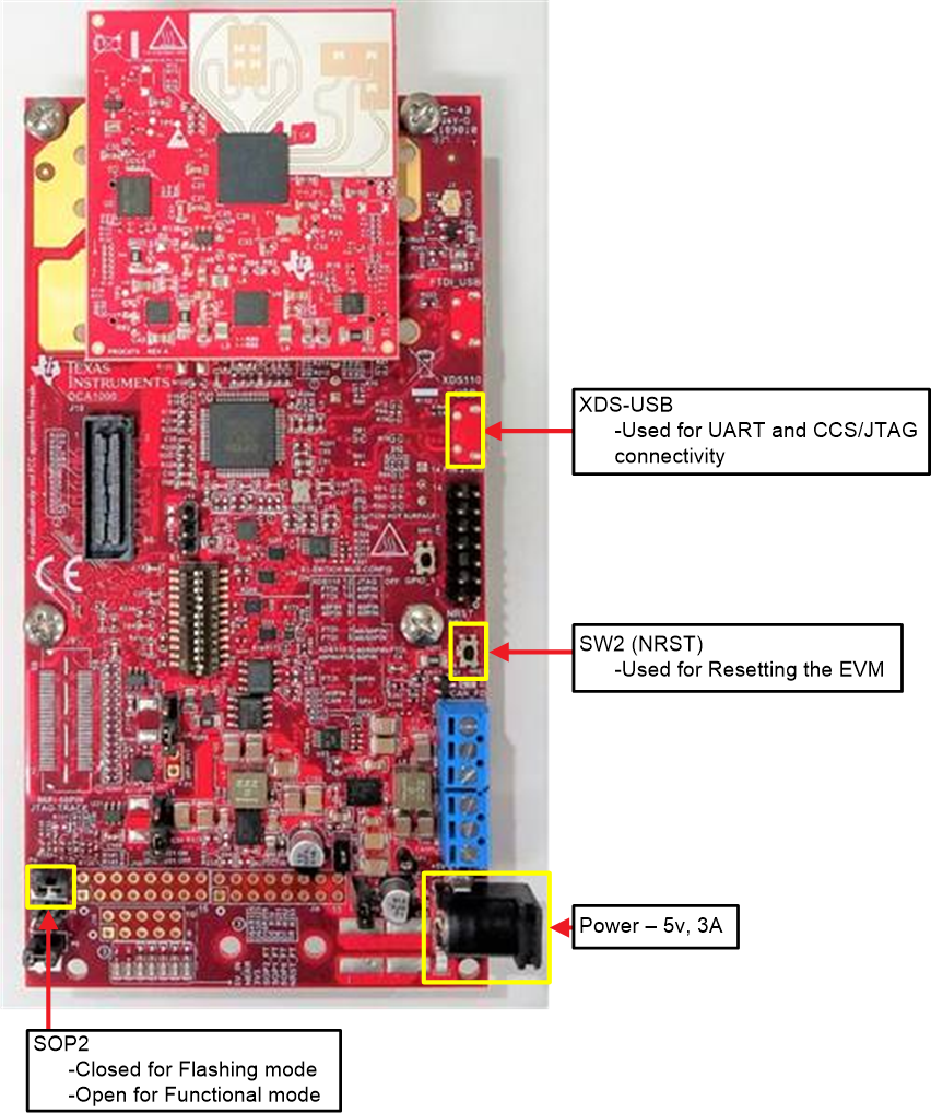
- Connect the XDS110-USB port on the IWR6843 mmWave EVM to the BBB USB port using the micro USB cable.
- Connect the HDMI monitor to the BBB using the micro HDMI cable (see Figure 10).
- Connect the 5-V, 3-A power supply to the IWR6843 mmWave EVM and press the SW2 (NRST) switch.
- Connect the BBB to the host computer (PC) using the FTDI-to-TTL debug cable.
- While keeping S2 (boot button) on BBB board pressed, connect the 5-V power supply and release the S2 (switch), once the 5-V power supply is connected. This is required to boot up the BBB from the microSD card.
- The BBB board should boot up and the Matrix GUI application should be seen on the screen (see Figure 11) (the Matrix GUI to Start takes a few minutes )
- Open the BBB COM port in TeraTerm or any other terminal emulation software and login as root (no password).
- Stop the Matrix GUI application and Weston scripts on the BBB board using the following command:
- Run the mmwavegesture_hmi application by using following instruction:
#/etc/init.d/weston stop
#mmwavegesture_hmi 1 -platform eglfs

