-
UCC28782 System Bring Up Guideline and Common Issues
- Trademarks
- 1 Initial Board Visual Inspection and Start-up Check
- 2 Typical System Operating Waveforms
- 3Typical System Protection Waveforms
- 4Common Issues and Solutions
- 5References
- IMPORTANT NOTICE
UCC28782 System Bring Up Guideline and Common Issues
Trademarks
All trademarks are the property of their respective owners.
1 Initial Board Visual Inspection and Start-up Check
Before powering up the design board, the first step is to thoroughly review the design to make sure all design parameters are calculated properly. The Excel Design Calculator is a helpful tools to check the accuracy of the design. It is recommended to do a visual inspection to check for the following:
- Solder bridges
- Solder balls
- Solder skips
- Cold solder joints
- Lifted pads
After visual inspection, the user can also use a multimeter to check the solder, Multimeter locked to diode location, Red probe connected to IC ground, Black probe connected to each pin. There should be a ~0.5 V-0.7 V voltage presents on the multimeter, if not, check solder of this pin. Figure 1-1 demonstrates probing UCC28782 Pins with a digital multimeter.
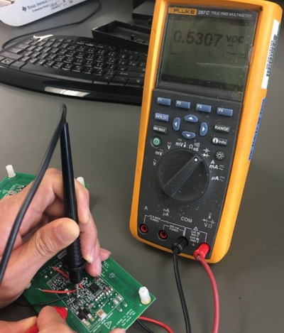 Figure 1-1 Probing UCC28782 Pins with a Digital Multimeter
When the solder inspection is complete, the board can input a low voltage, next steps are input short-circuit investigation / HV start circuits operation check / CS pin fault detection and input brown in voltage (startup voltage) detection:
- Step 1: Set input voltage source to Vin=5 Vrms while limiting its current to 0.5 A, measure the input current. After a brief low inrush peak current, there should be almost zero continuous input current, if an excessive current is observed, there may be a short or abnormally low impedance in the circuit.
- Step 2: If zero current is observed. Move to VDD
pin to check if HV start circuits working properly, 25 Vrms voltage implied on the
input, the captured waveform of VDD as shown in Figure 1-2: If VDD voltage can be charged to ~17.5 V, it indicates the HV start circuits
working normal. if not please refer to Debugging
UCC28780 ACF Converter Start-up Issues section 7.3, Start-up
Failure Due to VDD Clamped Low.
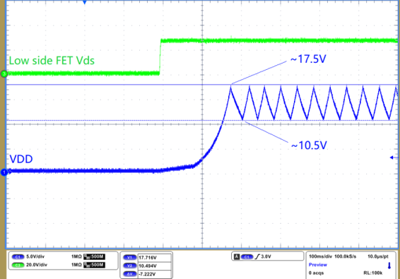 Figure 1-2 VDD Start Up and Hiccup at
Below Brown In Voltage
 - Step 3: Zoom in waveform at the point when VDD
reaches to its turn on threshold (17.5 V), capture low side driver signal PWML, if
only one pulse with a width of 2us is observed, see Figure 1-4, this is the correct behavior at the input voltage which lower than start up
voltage. Please refer to Debugging
UCC28780 ACF Converter Start-up Issues section 6.1 Observation
of Zero or Only One PWML Pulse.
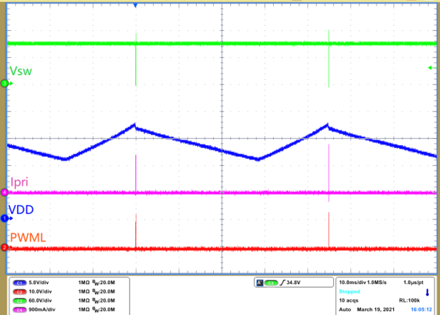 Figure 1-3 VDD Restart
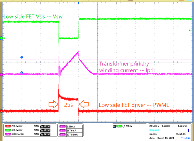 Figure 1-4 CS Pin Fault Detection -
Only 1 Pulse With 2us Width
 - Step 4: Gradually increase input voltage until
the user can see four consecutive pulses shown in Figure 1-5. The first pulse is for CS pin fault detection, the second, third, fourth pulses
are for brown in voltage detection. When the AC input voltage is lower than brown in
voltage. The user will always see four pulses at each VDD restart cycle. Further
increasing the input voltage until it is above the brown in voltage, the board
should be powered up if there is no protection occurring.
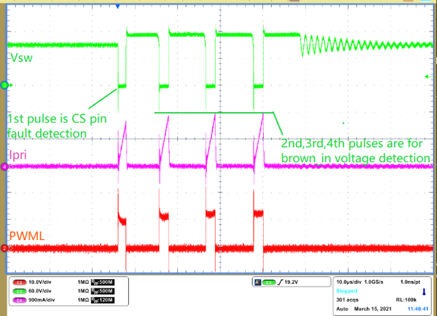 Figure 1-5 Brown-in Voltage Detection
– 4 Consecutive Pulses
2 Typical System Operating Waveforms
UCC28782 contains six modes of operation that summarized in UCC28782 data sheet Table 8-1. From no load to full load, the operation modes include Survival Mode, SBP2(Second StandBy Power Mode), SBP1, (First StandBy Power Mode) LPM (Low Power Mode), ABM (Adaptive Burst Mode), AAM (Adaptive Amplitude Modulation), The survival mode only kicks in when VDD voltage lower than the 13-V survival mode threshold and also performs the clamping capacitor balancing function to reduce the voltage stress of the secondary side rectifier. Typically, the system does not enter survival mode during regular load change, such as smooth load increase and decrease. The survival mode might kick in at a large output load remove, overshoot on output results in controller stop switching in a long time, then the VDD voltage might drop to touch the 13-V survival mode threshold. The following waveforms show each mode operation (no load to full load).
2.1 SBP2 Mode
At no load or very light load, PWMH is disabled and there are four PWML pulses in each burst packet. The peak current of each pulse is programmable through the resistance from IPC pin to ground. See Figure 2-1.
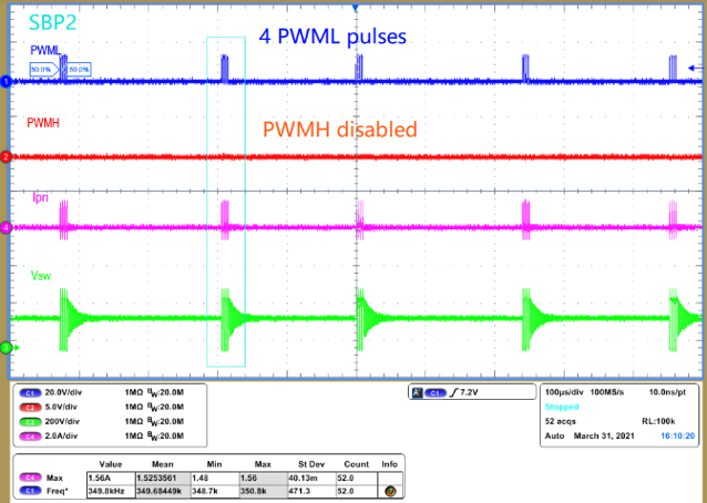 Figure 2-1 SBP2 Mode Operation
Waveform