-
Electrical Vehicle Improvements With a Highly Efficient Traction Inverter Design SPRADH3 September 2024 UCC5880-Q1 , UCC5881-Q1
-
Electrical Vehicle Improvements With a Highly Efficient Traction Inverter Design
Electrical Vehicle Improvements With a Highly Efficient Traction Inverter Design
Abstract
The traction inverter is one of the crucial parts of every electrical vehicle. The trend to go to 800V battery system and SiC devices with high switching frequency helped significantly in increasing inverter efficiency. To have a highly efficient system, both hardware and software need to have high performance, from the advanced technology ICs, layout, and precise sensors for the feedback signals, to the control algorithms and fast control loops that control the switches. Increased inverter efficiency means lower losses, but one of the main questions is what effect increased efficiency has on the electrical vehicle. In this paper, we show the systems requirements followed by high-power test results of 300kW, 800V traction inverter (TIDM-02014) and four key factors that are influenced by the inverter efficiency.
1 Introduction
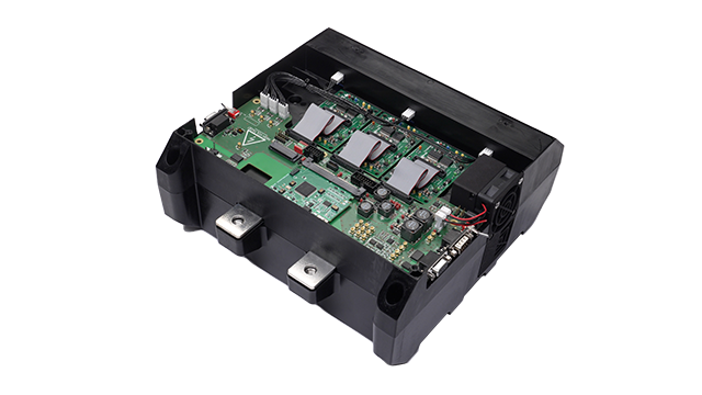
The TIDM-02014 is a 300kW, 800V Traction inverter reference design developed by Texas Instruments in a collaboration with Wolfspeed. Gate driver, control board and control cards developed by Texas Instruments are combined with Wolfspeed's XM3 power modules to have a high-performance traction inverter system. This inverter can be controlled with two different MCUs, the AM263P and the TMS320F280039C. Design files, technical documentations and the software packages are available at TI.com. The TIDM-02014 reference design is shown in Figure 1-1.
 Figure 1-1 TIDM-02014