How to Achieve Higher-reliability Isolation and a Smaller Solution Size with Solid-state Relays
Relays have been used as switches since before the transistor was invented. The ability to safely control high-voltage systems from lower-voltage signals, as is the case in isolation resistance monitoring, is necessary for the development of many automotive systems. While the technology of electromechanical relays and contactors has improved over the years, it is still challenging for designers to achieve their goals of lifetime reliability and fast switching speeds, along with low noise, shock vibration and power consumption.
Solid-state relays (SSRs) exhibit performance and cost benefits and are rated for different levels of isolation, whether basic or reinforced. SSRs also possess advantages over alternative technologies such as electromechanical relays and solid-state photorelays.
| Achieve higher reliability in your system | |

|
Learn more about our solid-state relay portfolio. |
Traditional Relay Switching Solutions
Electromechanical relays (EMRs) are common in high-voltage switching applications. EMRs employ the use of electromagnetic forces to mechanically switch contacts on and off. Given their mechanical nature, EMRs feature an incredibly low on-resistance; their contacts are essentially a metal-to-metal connection.
EMRs do have trade-offs when it comes to switching speeds and reliability. Moving parts inside the relay are a limiting factor, and switching speed is typically in the 5- to 15-ms range. Over time and with use, an EMR can experience failures such as arching, chattering and welding shut.
Unlike EMRs, photorelays have no moving parts and provide a high isolation voltage. Photorelays are an improvement over traditional EMRs; however, they also have design considerations such as limitations on the achievable power transfer as well as deterioration of the internal LED. Additionally, photorelays need an external current-limiting resistor and often use additional field-effect transistors (FETs) to manage the LED’s on or off state.
Higher-reliability Isolation Using SSRs
Solid-state relays from TI are available as switches (with integrated FETs) or drivers for controlling external FETs. Whether leveraging capacitive or magnetic isolation, TI’s isolated SSR portfolio can enable a design with basic or reinforced levels of isolation. TI’s TPSI2140-Q1 isolated switch and TPSI3050-Q1 isolated driver feature higher reliability and longevity compared to EMRs, since they do not experience mechanical deterioration over time. SSRs thus enable a 10 times higher lifetime reliability than traditional EMRs. TI’s SSRs can also switch in the microsecond range, orders of magnitude faster than EMRs.
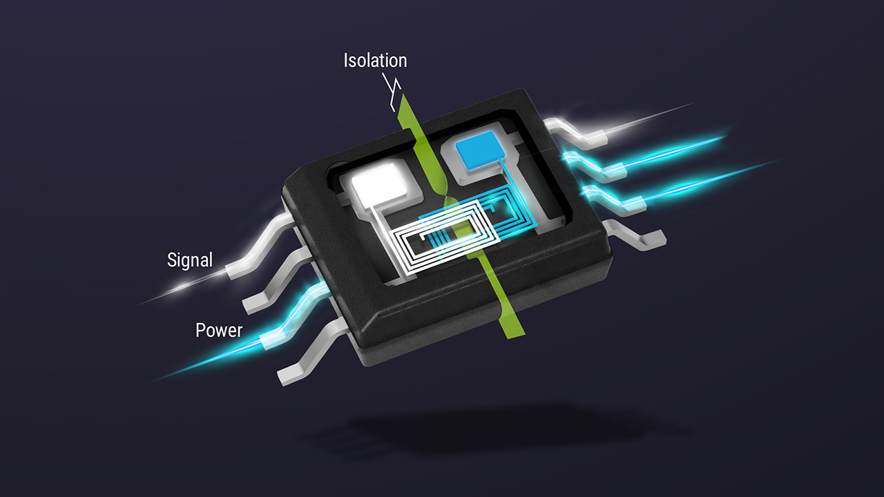
Since the TPSI3050-Q1 and TPSI2140-Q1 integrate power and signal transfer across a single isolation barrier, no secondary bias supply is necessary, making it possible to achieve a small solution size. Figure 1 illustrates the use of the TPSI2140-Q1 isolated switch in a high-voltage system, eliminating external components such as a bias supply and external control circuits.
 Figure 1 The TPSI2140-Q1 Isolated
Switch Reduces Solution Size in High-voltage Systems
Figure 1 The TPSI2140-Q1 Isolated
Switch Reduces Solution Size in High-voltage SystemsSolid-state relays such as the TPSI2140-Q1 and TPSI3050-Q1 also offer advantages over traditional photorelays and optocouplers. TI devices such as the TPSI2140-Q1 and TPSI3050-Q1 achieve better reliability over photorelays because there is no LED degradation. No external control circuits are necessary because the logic-level input can drive the system directly. Table 1 qualitatively compares these isolated switching technologies.
| Electromechanical relay | Photorelay or optical relay | TI solid-state relays | |
|---|---|---|---|
| Insulation material | Air or epoxy | Epoxy or polyimide | Polyimide or silicon dioxide |
| Dielectric strength (1 s) | ≈1 VRMS/µm ≈20 VRMS/µm |
≈20 VRMS/µm ≈300 VRMS/µm |
≈300 VRMS/µm ≈500 VRMS/µm |
| Advantages | Low resistance | Low electromagnetic interference (EMI) emissions | High speed (µs) Low power |
| Disadvantages | Slow speed (ms) mechanical wear, vibration/magnetic immunity |
Photodegradation and partial discharge | Must design to limit EMI |
| Operating ambient temperature | –40°C to 85°C | –40°C to 85°C | –40°C to 125°C |
| Cost | $$$ | $ | $ |
Conclusion
TI’s solid-state relays provide the highest dielectric strength at the fastest speed, highest operating temperature and lowest system cost. They also enable more reliable switching in a smaller package. Learn more about how we can help you simplify your design with our isolated switches and drivers in the additional resources below.
Additional Resources
- Read technical article, "How to design high-voltage systems with higher reliability while reducing solution size and cost".
- View our introduction to isolation trainings in our TI Precision Labs training series.
- Read our application notes:
- Evaluate the products with the TPSI3050Q1EVM and TPSI2140Q1EVM evaluation modules.
IMPORTANT NOTICE AND DISCLAIMER
TI PROVIDES TECHNICAL AND RELIABILITY DATA (INCLUDING DATASHEETS), DESIGN RESOURCES (INCLUDING REFERENCE DESIGNS), APPLICATION OR OTHER DESIGN ADVICE, WEB TOOLS, SAFETY INFORMATION, AND OTHER RESOURCES “AS IS” AND WITH ALL FAULTS, AND DISCLAIMS ALL WARRANTIES, EXPRESS AND IMPLIED, INCLUDING WITHOUT LIMITATION ANY IMPLIED WARRANTIES OF MERCHANTABILITY, FITNESS FOR A PARTICULAR PURPOSE OR NON-INFRINGEMENT OF THIRD PARTY INTELLECTUAL PROPERTY RIGHTS.
These resources are intended for skilled developers designing with TI products. You are solely responsible for (1) selecting the appropriate TI products for your application, (2) designing, validating and testing your application, and (3) ensuring your application meets applicable standards, and any other safety, security, or other requirements. These resources are subject to change without notice. TI grants you permission to use these resources only for development of an application that uses the TI products described in the resource. Other reproduction and display of these resources is prohibited. No license is granted to any other TI intellectual property right or to any third party intellectual property right. TI disclaims responsibility for, and you will fully indemnify TI and its representatives against, any claims, damages, costs, losses, and liabilities arising out of your use of these resources.
TI’s products are provided subject to TI’s Terms of Sale (www.ti.com/legal/termsofsale.html) or other applicable terms available either on ti.com or provided in conjunction with such TI products. TI’s provision of these resources does not expand or otherwise alter TI’s applicable warranties or warranty disclaimers for TI products.
Mailing Address: Texas Instruments, Post Office Box 655303, Dallas, Texas 75265
Copyright © 2023, Texas Instruments Incorporated