-
Optimize Your Automotive USB Short-to-battery Design - Part 2 SSZTB86 june 2016 TPD3S714-Q1 , TPD3S716-Q1
-
Optimize Your Automotive USB Short-to-battery Design - Part 2
Optimize Your Automotive USB Short-to-battery Design - Part 2
German Aguirre
With the USB Type-C connector becoming a new standard in the consumer world, USB is finding its way into more places in automotive infotainment systems. The propagation of USB ports across different locations in a car brings unique challenges when designing for the highest reliability. With faults such as short-to-battery, short-circuit and electrostatic discharge (ESD) conditions, automotive USB applications present use cases not found in other markets. Since power supplies run from the main vehicle battery, they are subjected to high voltage and current spikes generated during expected operation. Additionally, the downstream circuitry connected on VBUS and data lines from processors, USB hubs, charging controllers and load switches needs protection from short-to-battery events.
To protect against USB short-to-battery, an overvoltage protection circuit must be used to remove power from the system side when the voltage on the USB connector side rises above the overvoltage threshold. The overvoltage field-effect transistors (FETs) should have a fast response time that removes power from the system as quickly as possible to protect the upstream system on chip (SoC) from harmful voltage and current spikes. Additionally, the USB 2.0 specification requires the use of an overcurrent detection circuit to automatically limit current during overcurrent events. An internal switch can prevent excess current from damaging the upstream device, keeping the 5V rail stable and properly isolated from faults.
In part one of this two-part series; I illustrated the best way to protect USB circuits from short-to-battery faults. In this post, I will expand on the best way to optimize your automotive USB short-to-battery design.
Since car manufacturers may change the overall output-current requirements throughout the course of a project, a protection solution with an adjustable current limit provides more flexibility for system designers; allowing them to easily adjust the output current of their USB ports without having to qualify a new device. If you need to protect sensitive electronics against short-to-battery events and at the same time support current up to 2.4A, you may need a flexible short-to-battery chip.
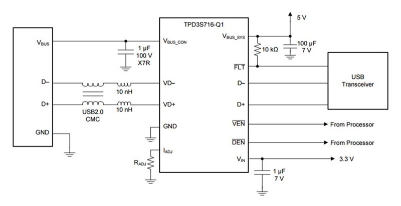
The TPD3S716-Q1 can enable charging for USB battery charging 1.2 (BC1.2), USB Type-C 5 V/1.5 A, and proprietary charging peripherals up to 2.4A. This automotive USB 2.0 interface protector is a single-chip solution for short-to-battery, short-circuit and ESD protection, with an adjustable current-limited load switch. The current-limit threshold for overcurrent protection is adjustable via an external resistor RADJ to the ground (GND) on the IADJ pin, as illustrated in Figure 1.
 Figure 1 Typical Application
Configuration for the TPD3S716-Q1
Figure 1 Typical Application
Configuration for the TPD3S716-Q1USB On-The-Go (OTG) is another specification commonly used in the automotive environment, since it enables USB devices to switch between the roles of host and client. This feature is important for USB high-speed applications where enabling the head unit to become an extension of the mobile media experience is necessary. In order for this to happen, the head unit has to be able to work in USB device mode accordingly.
The TPD3S716-Q1 has two enable inputs to turn the device’s internal FETs on and off. The VEN pin disables and enables the VBUS path and the DEN pin disables and enables the data path. Independent control of the VBUS and data paths allows you to configure this device for both USB host and client/OTG mode, as illustrated in Figure 2.
 Figure 2 Device Normal Operating Mode
Table for the
TPD3S716-Q1
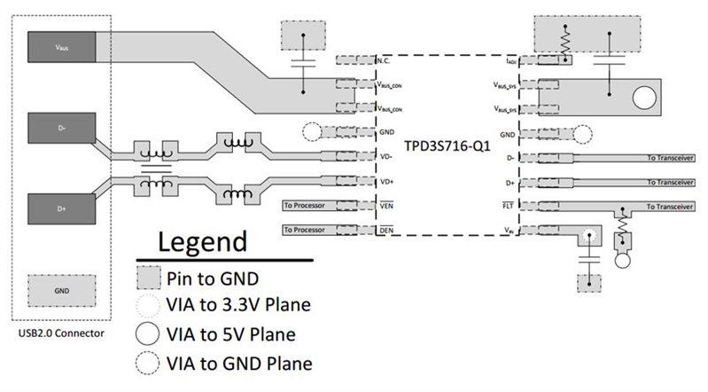
A package that is easy to route and small enough to fit within the dimensions of the USB connector is an important consideration for USB high-speed protection solutions for ease of layout and signal integrity. A flow-through pin mapping enables the signal trace to route straight through the package, as illustrated in Figure 3.
 Figure 3 Typical Layout Example for the
TPD3S716-Q1
Figure 3 Typical Layout Example for the
TPD3S716-Q1When designing to protect against USB short-to-battery, consider using a solution with adjustable current limit, OTG/client mode and flow-through routing. Doing so will allow you to make use of additional features not currently found in other short-to-battery solutions.
What considerations do you face when designing for USB 2.0 high-speed short-to-battery? Log in and leave a comment below.
Additional Resources
- Read my other blog post about how to protect automotive USB against short-to-battery faults.
- Check out the TI Designs Two-Port Automotive USB 2.0 Hub with Short-to-Battery Protection Reference Design.
- Read the white paper, “Designing USB for short-to-battery tolerance in automotive environments.”
- Check out the video, “Introducing the TPD3S714-Q1 for automotive USB short-to-battery.”
- Evaluate your design with the TPD3S716-Q1 evaluation module today for automotive USB 2.0 short-to-battery protection.
IMPORTANT NOTICE AND DISCLAIMER
TI PROVIDES TECHNICAL AND RELIABILITY DATA (INCLUDING DATASHEETS), DESIGN RESOURCES (INCLUDING REFERENCE DESIGNS), APPLICATION OR OTHER DESIGN ADVICE, WEB TOOLS, SAFETY INFORMATION, AND OTHER RESOURCES “AS IS” AND WITH ALL FAULTS, AND DISCLAIMS ALL WARRANTIES, EXPRESS AND IMPLIED, INCLUDING WITHOUT LIMITATION ANY IMPLIED WARRANTIES OF MERCHANTABILITY, FITNESS FOR A PARTICULAR PURPOSE OR NON-INFRINGEMENT OF THIRD PARTY INTELLECTUAL PROPERTY RIGHTS.
These resources are intended for skilled developers designing with TI products. You are solely responsible for (1) selecting the appropriate TI products for your application, (2) designing, validating and testing your application, and (3) ensuring your application meets applicable standards, and any other safety, security, or other requirements. These resources are subject to change without notice. TI grants you permission to use these resources only for development of an application that uses the TI products described in the resource. Other reproduction and display of these resources is prohibited. No license is granted to any other TI intellectual property right or to any third party intellectual property right. TI disclaims responsibility for, and you will fully indemnify TI and its representatives against, any claims, damages, costs, losses, and liabilities arising out of your use of these resources.
TI’s products are provided subject to TI’s Terms of Sale (www.ti.com/legal/termsofsale.html) or other applicable terms available either on ti.com or provided in conjunction with such TI products. TI’s provision of these resources does not expand or otherwise alter TI’s applicable warranties or warranty disclaimers for TI products.
Mailing Address: Texas Instruments, Post Office Box 655303, Dallas, Texas 75265
Copyright © 2023, Texas Instruments Incorporated