-
TPS54110 3V~6V 入力、1.5A、同期整流降圧型コンバータ
- 1 特長
- 2 アプリケーション
- 3 概要
- 4 改訂履歴
- 5 Device Information
- 6 Pin Configuration and Functions
- 7 Specifications
- 8 Detailed Description
- 9 Application and Implementation
- 10Layout
- 11デバイスおよびドキュメントのサポート
- 12メカニカル、パッケージ、および注文情報
- 重要なお知らせ
パッケージ・オプション
デバイスごとのパッケージ図は、PDF版データシートをご参照ください。
メカニカル・データ(パッケージ|ピン)
- PWP|20
サーマルパッド・メカニカル・データ
- PWP|20
発注情報
DATA SHEET
TPS54110 3V~6V 入力、1.5A、同期整流降圧型コンバータ
このリソースの元の言語は英語です。 翻訳は概要を便宜的に提供するもので、自動化ツール (機械翻訳) を使用していることがあり、TI では翻訳の正確性および妥当性につきましては一切保証いたしません。 実際の設計などの前には、ti.com で必ず最新の英語版をご参照くださいますようお願いいたします。
1 特長
- 内蔵 MOSFET スイッチにより、1.5A のソースまたはシンク電流を高効率で連続出力
- 可変出力電圧:0.9V~3.3V、精度1%
- 設計の柔軟性を高める外部補償機能
- 高速な過渡応答
- 広い PWM 周波数:固定 350kHz、550kHz、
または 280kHz~700kHz の範囲で可変 - ピーク電流制限とサーマル・シャットダウンにより負荷を保護
- 統合ソリューションにより基板面積と総コストを低減
2 アプリケーション
- 5V または 3.3V の低電圧、高密度の分散電源システム
- 高性能 DSP、FPGA、ASIC、マイクロプロセッサのポイント・オブ・ロード・レギュレーション
- ブロードバンド、ネットワーク、光通信インフラ
- 携帯型コンピュータ / ノート PC
3 概要
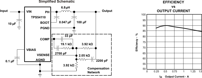
TPS54110 は、必要なアクティブ部品をすべて内蔵した低入力電圧、大出力電流の同期整流降圧型 PWM コンバータです。一覧の特長とともに、過渡条件で高い性能を発揮する真の高性能電圧エラー・アンプ、入力電圧が 3V に達するまでスタートアップを阻止する低電圧誤動作防止回路、内部的または外部的に設定される突入電流制限用スロースタート回路、プロセッサ/ロジックのリセット、フォルト通知、電源シーケンシングに便利なパワー・グッド出力を 1 チップに内蔵しています。
TPS54110 デバイスは、熱的に強化された 20 ピンの HTSSOP (PWP) PowerPAD™パッケージで供給されるため、かさばるヒートシンクは不要です。TI は、お客様が短期間の開発サイクルに対応して高性能電源をすばやく設計できるように、評価モジュールとその他の技術的サポートを提供しています。
製品情報(1)
| 型番 | パッケージ | 本体サイズ(公称) |
|---|---|---|
| TPS54110 | HTSSOP (20) | 6.50mm×4.40mm |
- 提供されているすべてのパッケージについては、このデータシートの末尾にある注文情報を参照してください。
Device Images
