JAJSBN1C March 2012 – October 2016 TPS62090 , TPS62091 , TPS62092 , TPS62093
PRODUCTION DATA.
- 1 特長
- 2 アプリケーション
- 3 概要
- 4 改訂履歴
- 5 Device Comparison Table
- 6 Pin Configuration and Functions
- 7 Specifications
-
8 Detailed Description
- 8.1 Overview
- 8.2 Functional Block Diagram
- 8.3
Feature Description
- 8.3.1 Enable and Disable (EN)
- 8.3.2 Softstart (SS) and Hiccup Current Limit During Startup
- 8.3.3 Voltage Tracking (SS)
- 8.3.4 Short Circuit Protection (Hiccup-Mode)
- 8.3.5 Output Discharge Function
- 8.3.6 Power Good Output (PG)
- 8.3.7 Frequency Set Pin (FREQ)
- 8.3.8 Undervoltage Lockout (UVLO)
- 8.3.9 Thermal Shutdown
- 8.3.10 Charge Pump (CP, CN)
- 8.4 Device Functional Modes
- 9 Application and Implementation
- 10Power Supply Recommendations
- 11Layout
- 12デバイスおよびドキュメントのサポート
- 13メカニカル、パッケージ、および注文情報
パッケージ・オプション
メカニカル・データ(パッケージ|ピン)
- RGT|16
サーマルパッド・メカニカル・データ
- RGT|16
発注情報
1 特長
- 入力電圧範囲: 2.5V~6V
- DCS-Control™
- 95%のコンバータ効率
- パワーセービング・モード
- 動作時の静止電流20µA
- 100%デューティ・サイクル動作により低いドロップアウト電圧を実現
- 標準スイッチング周波数2.8MHz/1.4MHz
- 出力電圧は0.8V~VINまで可変
- 固定出力電圧バージョン
- 出力放電機能
- 調整可能なソフト・スタート
- ヒカップ短絡保護
- 出力電圧トラッキング
- TPS62095とピン単位で互換
2 アプリケーション
- 分散型電源
- ノートPC、ネットブック
- ハードディスク・ドライブ(HDD)
- ソリッド・ステート・ドライブ(SSD)
- プロセッサの電源
- バッテリ駆動のアプリケーション
3 概要
TPS6209xデバイスは高周波数の同期整流降圧型コンバータで、サイズが小さく、高効率で、バッテリ駆動のアプリケーションに適したソリューションとなるよう最適化されています。最大の効率を実現するため、このコンバータはパルス幅変調(PWM)モードで動作します。公称スイッチング周波数は2.8MHz/1.4MHzで、負荷電流が小さいときには自動的にパワーセービング・モードの動作に移行します。分散型電源およびポイント・オブ・ロード・レギュレーションで使用するとき、他の電圧レールへの電圧トラッキングが可能で、10µFから150µFまで、さらにそれ以上の出力容量を許容できます。このデバイスは、DCS-Control™トポロジを使用して非常に優れた負荷過渡性能と、出力電圧の正確なレギュレーションを実現しています。
出力電圧のスタートアップ・ランプはソフトスタート・ピンにより制御されるため、スタンドアロンの電源またはトラッキング構成で動作できます。イネーブル・ピンおよびパワー・グッド・ピンの構成により、電源シーケンシングも可能です。パワーセービング・モードでは、デバイスは標準20µAの静止電流で動作します。パワーセービング・モードへの遷移は自動的かつシームレスに行われるため、負荷電流範囲の全体にわたって高い効率が維持されます。
製品情報(1)
| 型番 | パッケージ | 本体サイズ(公称) |
|---|---|---|
| TPS62090 | QFN (16) | 3.00mm×3.00mm |
| TPS62091 | ||
| TPS62092 | ||
| TPS62093 |
(1) 利用可能なすべてのパッケージについては、このデータシートの末尾にある注文情報を参照してください。
sp
sp
sp
sp
代表的なアプリケーションの回路図

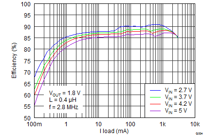
効率と出力電流との関係
