-
LM5118 電圧範囲の広い昇降圧コントローラ
- 1 特長
- 2 アプリケーション
- 3 概要
- 4 改訂履歴
- 5 Pin Configuration and Functions
- 6 Specifications
- 7 Detailed Description
-
8 Application and Implementation
- 8.1 Application Information
- 8.2
Typical Application
- 8.2.1 Design Requirements
- 8.2.2
Detailed Design Procedure
- 8.2.2.1 Custom Design With WEBENCH® Tools
- 8.2.2.2 R7 = RT
- 8.2.2.3 Inductor Selection, L1
- 8.2.2.4 R13 = RSENSE
- 8.2.2.5 C15 = CRAMP
- 8.2.2.6 Inductor Current Limit Calculation
- 8.2.2.7 C9 - C12 = Output Capacitors
- 8.2.2.8 D1
- 8.2.2.9 D4
- 8.2.2.10 C1 - C5 = Input Capacitor
- 8.2.2.11 C20
- 8.2.2.12 C8
- 8.2.2.13 C16 = CSS
- 8.2.2.14 R8, R9
- 8.2.2.15 R1, R3, C21
- 8.2.2.16 R2
- 8.2.2.17 Snubber
- 8.2.2.18 Error Amplifier Configuration
- 8.2.3 Application Curves
- 9 Power Supply Recommendations
- 10Layout
- 11デバイスおよびドキュメントのサポート
- 12メカニカル、パッケージ、および注文情報
- 重要なお知らせ
LM5118 電圧範囲の広い昇降圧コントローラ
1 特長
- 非常に広い入力電圧範囲: 3V~75V
- エミュレーションによるピーク電流モード制御
- 降圧と昇圧のモード間をスムーズに遷移
- スイッチング周波数を最高500kHzにプログラム可能
- 発振器の同期機能
- 高電圧バイアス・レギュレータを内蔵
- ハイサイドおよびローサイドのゲート・ドライバを内蔵
- ソフトスタート時間をプログラム可能
- 非常に低いシャットダウン電流
- イネーブル入力
- 広帯域幅のエラー・アンプ
- 1.5%のフィードバック・リファレンス精度
- サーマル・シャットダウン
- パッケージ: 20ピンのHTSSOP (露出パッド)
- WEBENCH® Power Designerにより、LM5118を使用するカスタム設計を作成
2 アプリケーション
産業用昇降圧電源
3 概要
LM5118は広い電圧範囲で動作する昇降圧スイッチング・レギュレータ・コントローラで、最小限の外付け部品で高性能かつコスト効率が高い昇降圧レギュレータを実装するために必要な、すべての機能が搭載されています。昇降圧トポロジにより、入力電圧が出力電圧より低くても高くても、出力電圧のレギュレーションが維持されるため、車載用アプリケーションには特に適しています。LM5118は、レギュレートされる出力電圧よりも入力電圧が十分に高いときは降圧レギュレータとして動作し、入力電圧が出力に近付くと、次第に昇降圧モードへ移行します。このデュアル・モード方式により、広い範囲の入力電圧においてレギュレーションが維持され、降圧モードで最適な変換効率を実現し、モード遷移の間も出力にグリッチが発生しません。この使いやすいコントローラには、ハイサイド降圧MOSFETと、ローサイド昇圧MOSFET用のドライバが含まれています。レギュレータの制御方法は、エミュレート電流ランプを使用した電流モード制御です。エミュレートされた電流モード制御を使用することで、パルス幅変調回路のノイズ感受性が低下し、入力電圧の高いアプリケーションに必要な、非常に小さいデューティ・サイクルを、高い信頼性で制御できます。さらに、電流制限、サーマル・シャットダウン、イネーブル入力の保護機能が搭載されています。このデバイスは、放熱を助ける露出ダイ接続パッドを備えて消費可能電力を増大させた、20ピンHTSSOPパッケージで供給されます。
製品情報(1)
| 型番 | パッケージ | 本体サイズ(公称) |
|---|---|---|
| LM5118 | HTSSOP (20) | 6.50mm×4.40mm |
- 提供されているすべてのパッケージについては、巻末の注文情報を参照してください。
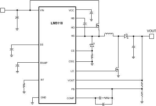
概略回路図

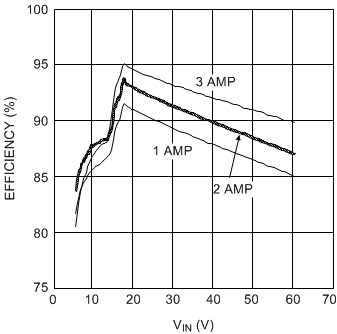
効率とVINおよびIOUTとの関係、VOUT = 12V

4 改訂履歴
Changes from I Revision (August 2014) to J Revision
- 車載用デバイスを独立のデータシート(SNVSAX9)に移動Go
- Moved the storage temp parameters to the Absolute Maximum RatingsGo
- Changed junction temperature range from: ±150°C max to: –40°C to 150°CGo
- Changed Handling Ratings table to ESD RatingsGo
- Moved the junction temperature ranges to the condition statementGo
- Removed the VOLL minimum valueGo
- Removed the VOLH minimum valueGo
Changes from H Revision (October 2013) to I Revision
- Changed 新しいTI標準に合わせてデータシートのフローとレイアウトを変更。以下のセクションを追加: 「アプリケーションと実装」、「電源に関する推奨事項」、「レイアウト」、「デバイスおよびドキュメントのサポート」、「メカニカル、パッケージ、および注文情報」Go
- Deleted footnote "These pins must not be raised above VIN."Go
Changes from G Revision (February, 2013) to H Revision
- Deleted VIN Range on Functional Block DiagramGo
- Changed Figure 19Go
- Changed Inductor Selection, L1 TextGo
- Changed Equation 15Go
- Changed Equation 16 Go
- Added Efficiency ParameterGo
- Changed II(PEAK) ValueGo
- Changed I2(PEAK) ValueGo
- Changed R13 = RSENSEText Go
- Added Equation 19 Go
- Added Equation 20 Go
- Changed Equation 21 Go
- Changed Equation 22 Go
- Changed R13(BUCK) ValueGo
- Changed R13(BUCK-BOOST) ValueGo
- Added Inductor Current Limit Calculation SectionGo
- Added Equation 24 Go
- Added Equation 26 Go
- Changed Equation 29 Go
- Changed ESRMAX ValueGo
- Deleted Previous Equation 17Go
- Deleted Previous Equation 18Go
- Changed C1 - C5 = Input Capacitor TextGo
- Changed R8, R9 TextGo
- Changed Equation 38 Go
- Changed R1, R3, C21 TextGo
- Changed Equation 40 Go
- Changed DMIN to DMAXGo
- Changed DMAX ValueGo
- Changed DC Gain(MOD) ValueGo
- Changed ESRZERO ValueGo
- Changed R4, C18, C17 TextGo
- Changed Figure 21Go
- Changed Figure 22Go
- Changed Figure 23Go
- Added Figure 24Go
- Added Figure 25Go
- Added Figure 26Go
Changes from F Revision (February 2013) to G Revision
- Changed layout of National Data Sheet to TI formatGo
5 Pin Configuration and Functions

Pin Descriptions
| PIN | TYPE(1) | DESCRIPTION | |
|---|---|---|---|
| NO. | NAME | ||
| 1 | VIN | P/I | Input supply voltage. |
| 2 | UVLO | I | If the UVLO pin is below 1.23 V, the regulator will be in standby mode (VCC regulator running, switching regulator disabled). When the UVLO pin exceeds 1.23 V, the regulator enters the normal operating mode. An external voltage divider can be used to set an undervoltage shutdown threshold. A fixed 5-µA current is sourced out of the UVLO pin. If a current limit condition exists for 256 consecutive switching cycles, an internal switch pulls the UVLO pin to ground and then releases. |
| 3 | RT | I | The internal oscillator frequency is set with a single resistor between this pin and the AGND pin. The recommended frequency range is 50 kHz to 500 kHz. |
| 4 | EN | I | If the EN pin is below 0.5 V, the regulator will be in a low power state drawing less than 10 µA from VIN. EN must be raised above 3 V for normal operation. |
| 5 | RAMP | I | Ramp control signal. An external capacitor connected between this pin and the AGND pin sets the ramp slope used for emulated current mode control. |
| 6 | AGND | G | Analog ground. |
| 7 | SS | I | Soft Start. An external capacitor and an internal 10-µA current source set the rise time of the error amp reference. The SS pin is held low when VCC is less than the VCC undervoltage threshold (< 3.7 V), when the UVLO pin is low (< 1.23 V), when EN is low (< 0.5 V) or when thermal shutdown is active. |
| 8 | FB | I | Feedback signal from the regulated output. Connect to the inverting input of the internal error amplifier. |
| 9 | COMP | O | Output of the internal error amplifier. The loop compensation network should be connected between COMP and the FB pin. |
| 10 | VOUT | I | Output voltage monitor for emulated current mode control. Connect this pin directly to the regulated output. |
| 11 | SYNC | I | Sync input for switching regulator synchronization to an external clock. |
| 12 | CS | I | Current sense input. Connect to the diode side of the current sense resistor. |
| 13 | CSG | I | Current sense ground input. Connect to the ground side of the current sense resistor. |
| 14 | PGND | G | Power Ground. |
| 15 | LO | O | Boost MOSFET gate drive output. Connect to the gate of the external boost MOSFET. |
| 16 | VCC | P/I/O | Output of the bias regulator. Locally decouple to PGND using a low ESR/ESL capacitor located as close to the controller as possible. |
| 17 | VCCX | P/I | Optional input for an externally supplied bias supply. If the voltage at the VCCX pin is greater than 3.9 V, the internal VCC regulator is disabled and the VCC pin is internally connected to VCCX pin supply. If VCCX is not used, connect to AGND. |
| 18 | HB | I | High-side gate driver supply used in bootstrap operation. The bootstrap capacitor supplies current to charge the high-side MOSFET gate. This capacitor should be placed as close to the controller as possible and connected between HB and HS. |
| 19 | HO | O | Buck MOSFET gate drive output. Connect to the gate of the high-side buck MOSFET through a short, low inductance path. |
| 20 | HS | I | Buck MOSFET source pin. Connect to the source terminal of the high-side buck MOSFET and the bootstrap capacitor. |
| — | EP | — | Solder to the ground plane under the IC to aid in heat dissipation. |