-
UCC27282 クロス導通保護機能を搭載し、スイッチング損失が小さい 3A 120V ハーフブリッジ・ドライバ
- 1 特長
- 2 アプリケーション
- 3 概要
- 4 Revision History
- 5 Pin Configuration and Functions
- 6 Specifications
- 7 Detailed Description
- 8 Application and Implementation
- 9 Power Supply Recommendations
- 10Layout
- 11Device and Documentation Support
- 12Mechanical, Packaging, and Orderable Information
- 重要なお知らせ
UCC27282 クロス導通保護機能を搭載し、スイッチング損失が小さい 3A 120V ハーフブリッジ・ドライバ
1 特長
- ハイサイド / ローサイド構成の 2 つの N チャネル MOSFET を駆動
- 5V (標準値) の低電圧誤動作防止
- 入力インターロック
- イネーブル / ディスエーブル機能付き、DRC パッケージ
- 16ns (標準値) の伝搬遅延
- 立ち上がり時間 12ns、立ち下がり時間 10ns (1.8nF 負荷時)
- 1ns (標準値) の遅延マッチング
- 入力の負電圧の絶対最大定格:-5V
- HS の負電圧の絶対最大定格:-14V
- ±3A のピーク出力電流
- 絶対最大ブート電圧:120V
- ディスエーブル時の低消費電流 (7µA)
- ブートストラップ・ダイオードを内蔵
- 接合部温度 -40℃~140℃で動作を規定
2 アプリケーション
- テレコムおよび商業用電源
- モータ・ドライブおよび電動工具
- 補助インバータ
- ハーフブリッジおよびフルブリッジ・コンバータ
- アクティブ・クランプ・フォワード・コンバータ
- 高電圧同期降圧コンバータ
- Class-D オーディオ・アンプ
 アプリケーション概略図
3 概要
UCC27282 は、100V の最大スイッチ・ノード (HS) 電圧定格を持つ堅牢な N チャネル MOSFET ドライバです。ハーフブリッジまたは同期整流降圧構成に基づくトポロジで 2 つの N チャネル MOSFET を制御できます。UCC27282 はピーク・ソースおよびシンク電流が 3A であり、プルアップおよびプルダウン抵抗も小さいため、MOSFET のミラー・プラトー遷移中のスイッチング損失を最小限に抑えて大電力 MOSFET を駆動できます。各入力が電源電圧と無関係であるため、UCC27282 はアナログ・コントローラともデジタル・コントローラとも組み合わせて使用できます。
入力ピンと HS ピンは大きな負の電圧に耐えられるため、システムの堅牢性が強化されます。入力インターロックにより、ノイズの大きなアプリケーションにおいて、さらに堅牢性とシステムの信頼性が向上します。イネーブルおよびディスエーブル機能により、ドライバの消費電力を低減することでシステムの柔軟性をさらに高めることができ、システム内のフォルト・イベントに応答できます。5V UVLO により、システムは低いバイアス電圧で動作できます。これは多くの高周波数アプリケーションに不可欠で、特定の動作モードでシステム効率を向上できます。伝搬遅延が短く、遅延マッチング仕様によりデッドタイムの要件が最小化されるため、さらに効率が向上します。
ハイサイドとローサイド両方のドライバ段に低電圧誤動作防止 (UVLO) 機能があり、VDD 電圧が指定のスレッショルドを下回ると、出力が強制的に LOW になります。内蔵のブートストラップ・ダイオードにより、多くのアプリケーションでは別の外付けダイオードが不要になるため、基板面積の削減とシステム・コストの低減に役立ちます。UCC27282 は小型のパッケージで供給されるため、高密度の設計が可能です。
| 部品番号 | パッケージ (サイズ) |
|---|---|
| UCC27282 | SON10 (3mm × 3mm) |
| SOIC8 (6mm × 5mm) | |
| SON8 (4mm x 4mm) | |
| SON10 (4mm × 4mm) |
4 Revision History
Changes from Revision A (January 2020) to Revision B (May 2022)
- 「製品情報」表に SON 8 ピン DRM および SON 10 ピン DPR パッケージを追加Go
- Added SON 8-Pin DRM and SON 10-pin DPR package images and updated the Pin Functions table.Go
- Added SON 8-pin DRM and SON 10-pin DPR packages to Thermal Information.Go
- Updated typcal peak pullup/pulldown current from +2.5A/-3.5A to ±3A in Electrical CharacteristicsGo
- Updated IHBS typical leakage to 5.0μA and test voltage from 110V to 100V in Electrical CharacteristicsGo
5 Pin Configuration and Functions
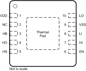
 Figure 5-1 DRC Package10-Pin VSON With Exposed Thermal PadTop View
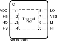
 Figure 5-3 DRM Package8-Pin SONTop View
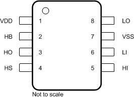
 Figure 5-2 D Package8-Pin SOICTop View
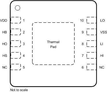
 Figure 5-4 DPR Package10-Pin SONTop View
| PIN | I/O(1) | DESCRIPTION | |||||
|---|---|---|---|---|---|---|---|
| Name | D | DRC | DRM | DPR | |||
| EN | n/a | 6 | n/a | n/a | I | Enable input. When this pin is pulled high, it will enable the driver. If left floating or pulled low, it will disable the driver. 1 nF filter capacitor is recommended for high-noise systems. | |
| HB | 2 | 3 | 2 | 2 | P | High-side bootstrap supply. The bootstrap diode is on-chip but the external bootstrap capacitor is required. Connect positive side of the bootstrap capacitor to this pin. Typical recommended value of HB bypass capacitor is 0.1 μF, This value primarily depends on the gate charge of the high-side MOSFET. When using external boot diode, connect cathode of the diode to this pin. | |
| HI | 5 | 7 | 5 | 7 | I | High-side input. | |
| HO | 3 | 4 | 3 | 3 | O | High-side output. Connect to the gate of the high-side power MOSFET or one end of external gate resistor, when used. | |
| HS | 4 | 5 | 4 | 4 | P | High-side source connection. Connect to source of high-side power MOSFET. Connect negative side of bootstrap capacitor to this pin. | |
| LI | 6 | 8 | 6 | 8 | I | Low-side input | |
| LO | 8 | 10 | 8 | 10 | O | Low-side output. Connect to the gate of the low-side power MOSFET or one end of external gate resistor, when used. | |
| NC | n/a | 2 | n/a | 5,6 | — | Not connected internally. | |
| VDD | 1 | 1 | 1 | 1 | P | Positive supply to the low-side gate driver. Decouple this pin to VSS. Typical decoupling capacitor value is 1 μF. When using an external boot diode, connect the anode to this pin. | |
| VSS | 7 | 9 | 7 | 9 | G | Negative supply terminal for the device which is generally the system ground. | |
| Thermal pad | n/a | - | - | - | — | Connect to a large thermal mass trace (generally IC ground plane) to improve thermal performance. This can only be electrically connected to VSS. | |