DLPA060B July 2015 – November 2024 DLP7000UV , DLP9000XUV , DLP9500UV
5.1 Incoherent Sources (Lamps and LEDs)
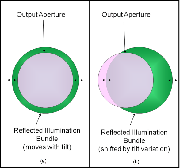
For broadband and LED sources(2) that precisely match the size of the DMD reflected output bundle to the input illumination bundle, DMD micromirror tilt variations can shift the reflected bundle such that reflected light spills to the side and is obscured by the output aperture as shown in the panels of Figure 5-3. This results in undesired loss of total output brightness with an added potential for image brightness non-uniformity.
(2) When a DMD is used with incoherent sources, a filter which nearly extinguishes all wavelengths below the DMD minimum specified wavelength must be used in the illumination path to the DMD (see the individual data sheet specification). Some LEDs do not have significant spectral content below the DMD minimum specified wavelength, thereby obviating the need for a filter.
 Figure 5-3 Small Output Aperture
The best way to capture all of the light with tolerance for micromirror tilt variation is to make the illumination bundle smaller than the output aperture. This allows all of the light to be captured, as illustrated in Figure 5-4:
 Figure 5-4 Reflected Illumination Movement with Tilt Variation
For the current UVA capable DMDs, the tilt variation specification is ±1°. At the output aperture the reflected illumination moves 2x this amount, ±2°, since the reflected rays move 2x the movement of the reflecting surface. The output aperture is recommended to be 4° larger in diameter than the illumination bundle to encompass this range (–2° to +2°). This example assumes a nominal 12° illumination and does not include adjusting the illumination angle as recommended in the previous Section 4 section.
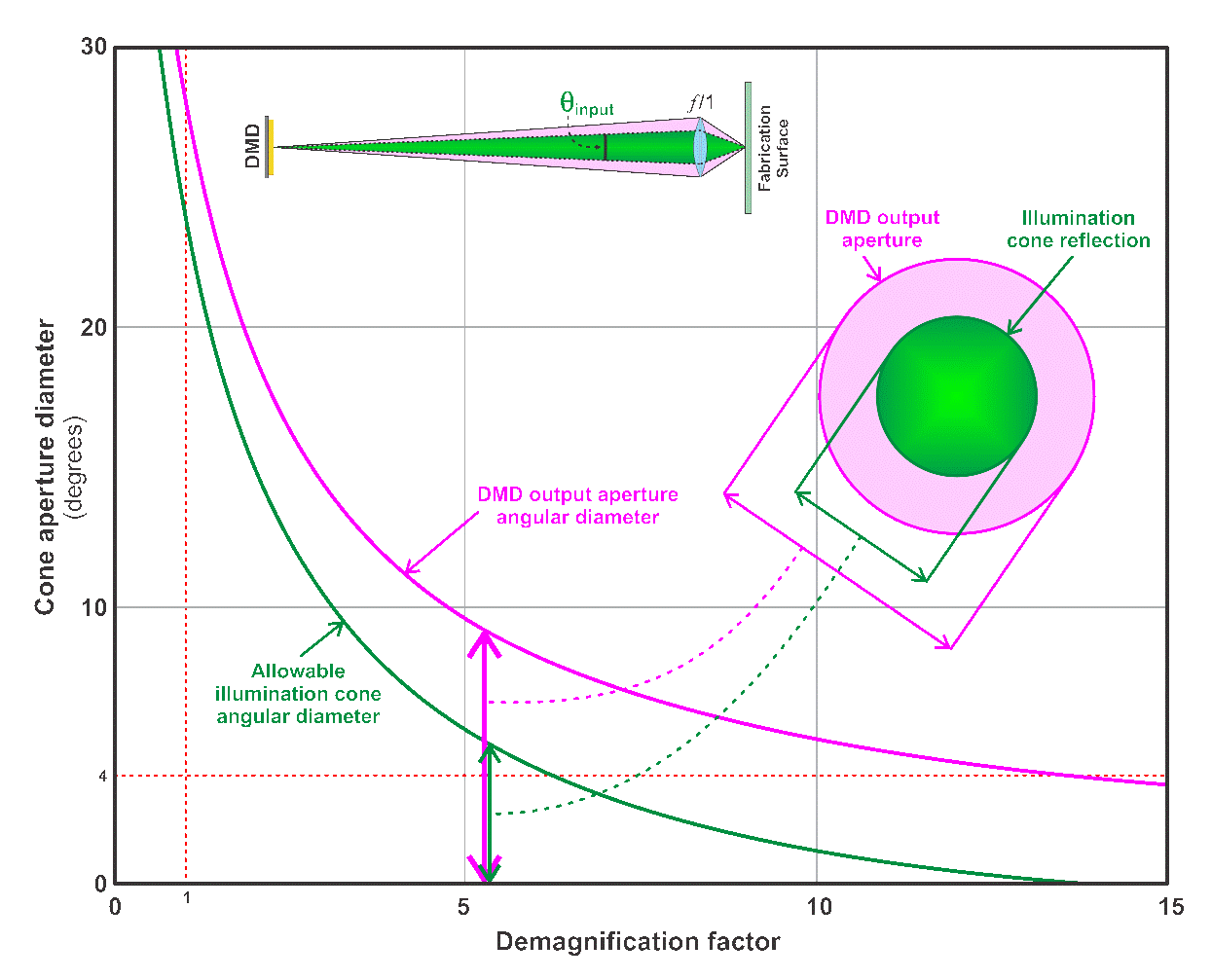
Therefore, an effective limit exists on the largest ƒ-number (smallest aperture) at the output that can be achieved to provide the 4° of tolerance. Even for an excellent collimated illumination beam with an angular extent of zero degrees, the aperture has an ƒ/14.3 equivalent, which is a cone with an angular diameter of 4°.
This results in a practical limit on the demagnification that can be reached with this tolerance. Optics with an ƒ-number of less than one are very difficult to build. If a limit of ƒ/1 is used, then a demagnification of 13x is the largest possible demagnification. The graph in Figure 5-5 shows two curves. The magenta curve is the angular diameter of the cone at the DMD output aperture that results in an ƒ/1 cone at the fabrication surface. The green curve is the allowable angular diameter of the illumination bundle that maintains a 4° margin between the illumination bundle and the output aperture. Note that the allowable illumination cone diameter reaches zero just past 13x demagnification.
 Figure 5-5 DMD Output Aperture Diameter vs Demagnification
Equation 2 approximates the maximum achievable demagnification for a given ƒ-number.

where:
- θinput is the angular extent of the input illumination bundle.
In summary, incoherent sources have two limits when used in high demagnification systems. The output is recommended to have an ƒ-number of less than ƒ/14.3 and a demagnification of 13x or less. In practice, the angular diameter of the illumination bundle is several degrees so that either some aperture margin is sacrificed or a lower demagnification chosen. If the optical design includes options for independently aligning the DMD with the output optics and illumination source angle, higher f/# and demagnification values are possible.