DLPA078C February 2017 – October 2024 DLP160AP , DLP160CP , DLP2000 , DLP2010 , DLP230GP , DLP230KP , DLP230NP , DLP3010 , DLP3310 , DLP4710 , DLP471TP , DLPC3420 , DLPC3421
2.6 Offset
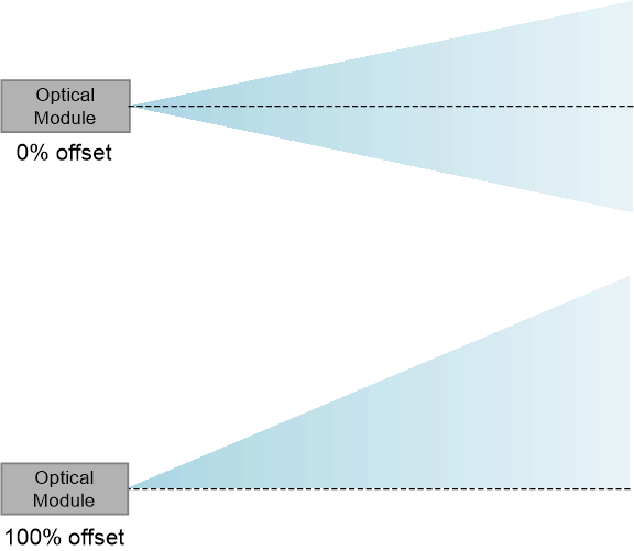
Offset describes the projected light path after light exits the projection lens. A 0% offset means the light is evenly distributed above and below the lens axis after exiting the projection lens. A 100% offset keeps the top of the image aligned with the lens axis keeping the bottom of the image coincident with the projection lens axis. A 100% or higher offset (for example, tilted up) is most common in order to avoid sending the bottom part of a projected image into the surface on which the product is resting. However, some applications prefer a 0% offset, allowing for thinner optical modules. For more information regarding lens offset, refer to slide 70 of the DLP Optical Design Guidelines presentation.
 Figure 2-4 0% Offset and 100%
Offset