DLPA078C February 2017 – October 2024 DLP160AP , DLP160CP , DLP2000 , DLP2010 , DLP230GP , DLP230KP , DLP230NP , DLP3010 , DLP3310 , DLP4710 , DLP471TP , DLPC3420 , DLPC3421
2.2 Size
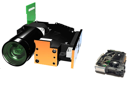
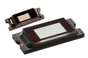
DLP Displays projection optical modules vary in size (see Figure 2-1), accomadating a wide range of application. The size of a DLP optical module primarily depends on the DMD size (see Figure 2-2), optical design, and illumination size. In general, optical module size increases with brightness capability. Modules may include heat sinks, with one typically on the DMD and another on each LED. The size of the heat sink is mainly driven by the power consumption and efficiency of the illumination in the optical module.
Performance requirements and optical design layout affect the size and shape of an optical module. Light can be folded (that is, bounced back and forth off mirrors) to reduce specific dimensions such as depth or height. Additionally, the projection lens size is affected by the throw ratio and image offset: shorter throw ratios and higher offsets typically result in lager modules. For additional information on projection lens considerations, see slides 65 - 73 of the DLP Optical Design Guidelines presentation.
 Figure 2-1 75-mm DLP4501 Optical Module
(left) compared to a 25-mm DLP2010 Optical Module (right)
 Figure 2-2 0.2-inch DLP2010 Diagonal DMD
compared to a 0.45-inch DLP4501 Diagonal DMD